
- PWM pins: D3, D5, D6, D9, D10 and D11, marked
~on the board. - I2C: SDA A4, SCL A5. SPI: SS D10, MOSI D11, MISO D12, SCK D13. Serial: RX D0, TX D1.
- Analog inputs: A0-A7. A6 and A7 are analog only and cannot be used as digital pins.
- External interrupts: D2 and D3 only. Built-in LED: D13.
- Power: USB, VIN (7-12 V) or regulated 5 V. Up to 20 mA per pin and 50 mA from the 3V3 pin.
- Will not upload? On a clone, try Tools > Processor > ATmega328P (Old Bootloader) first.
The Arduino Nano puts the same ATmega328P as the Uno on a 45 x 18 mm board. It plugs straight into a breadboard, weighs 7 grams, and runs almost every Uno sketch unchanged, which is why projects prototyped on an Uno so often end up on a Nano.
This guide starts with the pinout diagram, then covers the PWM, I2C, SPI and analog pins, the A6 and A7 trap, your power options, and the upload error that clone boards are known for. If you have not installed the IDE yet, start with our Arduino IDE download guide.
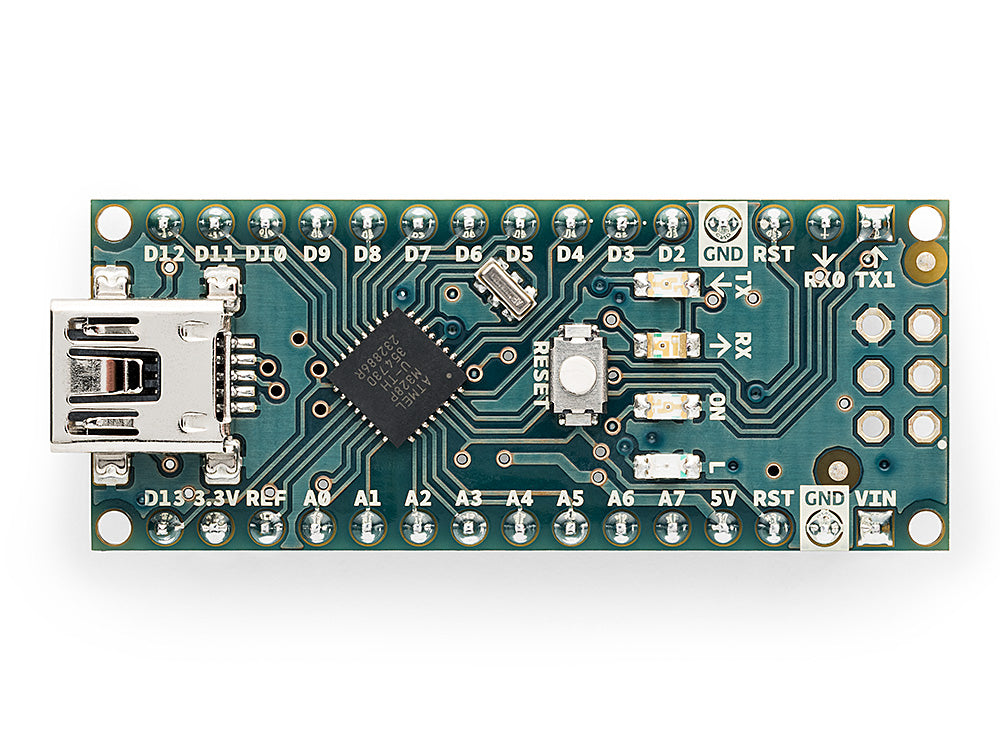
Arduino Nano Pinout Diagram
This is probably what you came for, so it goes first:

The diagram shows the component side with USB at the top. Here is every function in one table:
| Pin | Primary function | Also | Note |
|---|---|---|---|
| D0 / RX0 | UART RX | Digital | USB serial line, leave free when uploading |
| D1 / TX1 | UART TX | Digital | USB serial line, leave free when uploading |
| D2 | Digital | INT0 | External interrupt |
| D3 | Digital | PWM, INT1 | External interrupt, tone() disturbs its PWM |
| D4 | Digital | Free | |
| D5, D6 | Digital | PWM | 980 Hz |
| D7, D8 | Digital | Free | |
| D9 | Digital | PWM | The Servo library disables its PWM |
| D10 | Digital | PWM, SPI SS | The Servo library disables its PWM |
| D11 | Digital | PWM, SPI MOSI | tone() disturbs its PWM |
| D12 | Digital | SPI MISO | |
| D13 | Digital | SPI SCK | Built-in LED attached |
| A0-A3 | Analog | Digital D14-D17 | |
| A4 | Analog | I2C SDA, D18 | |
| A5 | Analog | I2C SCL, D19 | |
| A6, A7 | Analog | None | analogRead only |
To search pins by function, our Arduino pinout tool shows the Uno, Nano, Mega and ESP32 on one screen.
Arduino Nano Specs
| Spec | Value |
|---|---|
| Microcontroller | ATmega328P, 16 MHz |
| Operating voltage | 5 V |
| Flash | 32 KB, with 30,720 bytes available for sketches in the Arduino IDE |
| SRAM / EEPROM | 2 KB / 1 KB |
| Digital pins | 20 (D0-D13 and A0-A5) |
| Analog inputs | 8 (A0-A7), 10-bit |
| PWM | 6 pins |
| USB | Mini-B (official board) |
| Size and weight | 45 x 18 mm, 7 g |
Compared with the Uno, the Nano adds two analog inputs (A6, A7), drops the DC barrel jack and uses mini-B USB. The other pin functions sit on the same numbers, so moving an Uno sketch usually only means rewiring it.
PWM Pins
analogWrite works only on D3, D5, D6, D9, D10 and D11. The range is 0-255, so 127 is roughly a 50 percent duty cycle. The frequency is about 980 Hz on D5 and D6 and about 490 Hz on the rest.
Two libraries cause surprises here:
- The Servo library takes over Timer1, which disables PWM on D9 and D10. Wiring a servo to those pins is fine. Calling
analogWriteon them is the problem. tone()uses Timer2, so PWM on D3 and D11 misbehaves while a tone is playing.
A short LED fade example:
const int ledPin = 9;

void setup() {
  pinMode(ledPin, OUTPUT);
}

void loop() {
  for (int value = 0; value <= 255; value++) {
    analogWrite(ledPin, value);
    delay(5);
  }
  for (int value = 255; value >= 0; value--) {
    analogWrite(ledPin, value);
    delay(5);
  }
}
Do not forget the series resistor. Our LED resistor calculator gives you the value.
Analog Pins and the A6, A7 Trap
analogRead maps 0-5 V to a number from 0 to 1023, so each step is about 4.9 mV. A0-A5 also work as digital pins: digitalWrite(A0, HIGH) is valid because A0 is really D14.
A6 and A7 are different. On the ATmega328P’s TQFP package these two channels connect only to the analog-to-digital converter, with no digital I/O circuitry behind them. In practice, three things will not work:
digitalRead(A6)anddigitalWrite(A6, ...)- The internal resistor via
pinMode(A7, INPUT_PULLUP) - Reading a button wired straight to A6 or A7 (you need an external resistor and
analogRead)
void setup() {
  Serial.begin(9600);
}

void loop() {
  int raw = analogRead(A6);
  float volts = raw * 5.0 / 1023.0;
  Serial.print(raw);
  Serial.print(" = ");
  Serial.print(volts);
  Serial.println(" V");
  delay(500);
}
Never connect anything above 5 V directly to an analog pin. Pick the right resistors with our voltage divider calculator.
The AREF pin sets the top of the analog range. If you wire in an external reference, call analogReference(EXTERNAL) before any analogRead. Otherwise the external voltage is shorted against the internal reference, which can damage the chip.
I2C and SPI Pins
I2C is fixed: SDA = A4, SCL = A5. Wire.begin() takes no pin arguments on this board. While I2C is active, A4 and A5 are not available as analog inputs, which leaves A0-A3, A6 and A7.
The most common I2C module is the 0.96 inch SSD1306 OLED:
#include <Wire.h>
#include <Adafruit_GFX.h>
#include <Adafruit_SSD1306.h>

Adafruit_SSD1306 display(128, 64, &Wire, -1);

void setup() {
  display.begin(SSD1306_SWITCHCAPVCC, 0x3C);
  display.clearDisplay();
  display.setTextSize(2);
  display.setTextColor(SSD1306_WHITE);
  display.setCursor(0, 20);
  display.println("Nano");
  display.display();
}

void loop() {}
It takes four wires: VCC to 5V, GND to GND, SDA to A4, SCL to A5. See our Arduino OLED SSD1306 guide for the details. The 128x64 frame buffer takes half of the Nano’s SRAM (1 KB), so budget for it. For an I2C 16x2 LCD, the I2C LCD code generator writes the sketch for you.
SPI pins are fixed as well: SS D10, MOSI D11, MISO D12, SCK D13. Two details matter. Set D10 to OUTPUT even if you use it for something else, because if it is an input and goes LOW the chip can drop out of SPI master mode. And since the built-in LED shares D13, a flickering LED during SPI traffic is normal.
Digital Pins and Interrupts
The pins you can use freely are D2-D12. The restricted ones:
- D0 and D1: Wired to the USB serial line. Uploading with a module attached often fails, and they clash with
Serial. Avoid them if you can. - D13: Fine as an output, but the LED makes it a poor first choice for reading a button.
- External interrupts:
attachInterruptworks only on D2 and D3. Keep them free if you plan to add an encoder or a fast counter.
const int button = 2;
volatile bool pressed = false;

void onPress() {
  pressed = true;
}

void setup() {
  Serial.begin(9600);
  pinMode(button, INPUT_PULLUP);
  attachInterrupt(digitalPinToInterrupt(button), onPress, FALLING);
}

void loop() {
  if (pressed) {
    pressed = false;
    Serial.println("Button pressed");
  }
}
Our HC-SR04 guide works as is on a Nano if you want to add a distance sensor.
Power Pins: VIN, 5V, 3V3
| Pin | What it does | Limit |
|---|---|---|
| USB | Uploading and 5 V power | Whatever the computer port supplies |
| VIN | Regulated external power input | 7-12 V recommended |
| 5V | Regulated 5 V output or input | Never apply more than 5.5 V |
| 3V3 | 3.3 V output | 50 mA max |
| GND | Common ground | Share it with external modules |
| RST | Pull LOW to restart the board | Both RST pins are the same line |
The limit for a single pin is 20 mA. The ATmega328P datasheet lists 40 mA as an absolute maximum, but that is a damage threshold, not an operating value. Drive relays and motors through a transistor or a driver module, never directly from a pin.
Arduino’s own documents disagree slightly: the pinout says 7-12 V for VIN and the user manual says 7-15 V. We recommend staying at or below 12 V, since the excess turns into heat in the regulator. Feed in 12 V and draw 100 mA from the 5V rail, and the regulator burns (12 - 5) x 0.1 = 0.7 W. That is noticeable heat for such a small part.
How much current can the 5V pin supply? It depends on the source, and Arduino does not publish a firm figure. On USB the port’s limit decides, on VIN the regulator’s temperature does. The safe approach is to power servos and LED strips from a separate 5 V supply and share only GND.
For battery projects, our battery life calculator estimates runtime.
Clone Boards and the CH340 Driver
Most cheap Nanos on the market are clones. The pin layout and code are identical. What changes is on the USB side:
| Official Nano | Typical clone | |
|---|---|---|
| USB serial chip | FT232RL | CH340 |
| USB connector | Mini-B | Mini-B or USB-C |
| Bootloader | New on current boards | Often old |
If a CH340 board shows up as “USB2.0-Serial” on Windows without opening a port, install WCH’s CH341SER driver. Windows 11 usually installs it by itself. If the driver is in place and there is still no port, the cable is the usual suspect: charge-only USB cables have no data lines.
Arduino Nano Not Uploading

The error you will see most often is this one:
avrdude: stk500_getsync() attempt 1 of 10: not in sync: resp=0x00
The cause is rarely a dead board. It is usually the wrong speed. The Arduino AVR Boards package has two options for the Nano, and they upload at different rates:
| Tools > Processor | Upload speed | Used by |
|---|---|---|
| ATmega328P | 115200 baud | Boards with the new bootloader |
| ATmega328P (Old Bootloader) | 57600 baud | Boards with the old bootloader, common on clones |
If one fails, try the other, it cannot hurt the board. If neither works, unplug anything on D0 and D1 and try another USB port. On some boards, pressing RESET the moment the upload message appears also helps. A truly corrupted bootloader can be rewritten through the ICSP header at the end of the board. Our Optiboot article explains what that bootloader does.
Other symptoms:
| Symptom | Cause and fix |
|---|---|
| Garbage characters in the Serial Monitor | Serial.begin speed does not match the monitor |
| D13 LED blinks on its own | Bootloader or SPI traffic, this is normal |
digitalRead(A6) always returns the same value | A6 is not digital, use analogRead |
| Board disconnects on every upload | Weak USB cable, or the load draws too much current |
| Upload fails with a module attached | D0 or D1 is busy, unplug the module |
Which Nano? Boards With Similar Names
“Nano” is now a family, not a single board. This guide covers the classic ATmega328P Nano. The others share the form factor but are not the same board:
| Board | Chip | Pin voltage | Good for |
|---|---|---|---|
| Arduino Nano | ATmega328P | 5 V | Learning, 5 V sensors, wide library support |
| Nano Every | ATmega4809 | 5 V | More memory in the same form factor |
| Nano R4 | Renesas RA4M1 | 5 V | New projects that want 5 V and USB-C |
| Nano 33 IoT | SAMD21 | 3.3 V | Wi-Fi and Bluetooth |
| Nano ESP32 | ESP32-S3 | 3.3 V | Wi-Fi, Bluetooth and more processing power |
Do not feed 5 V signals into the 3.3 V boards. Wiring diagrams written for the classic Nano will not transfer to them directly.
Uno or Nano comes down to this: the Uno for trying shields on a desk, the Nano for breadboards and small permanent builds. If you need Wi-Fi, do not force it onto a Nano. An ESP32 DevKit or ESP32-C3 SuperMini is a better starting point. If you can work at 3.3 V and want far more memory, the Raspberry Pi Pico is also a good pick.
FAQ
Which pins are PWM on the Arduino Nano? D3, D5, D6, D9, D10 and D11, marked ~ on the board. analogWrite works only on these six pins, with a range of 0-255.
Which pins are SDA and SCL on the Arduino Nano? SDA is A4 and SCL is A5. They are tied to the hardware, so they cannot be changed and Wire.begin() takes no pin arguments.
Can A6 and A7 be used as digital pins on the Nano? No. These two pins can only be read with analogRead. digitalRead, digitalWrite and the internal pull-up do not work on them.
What voltage can I apply to the Arduino Nano VIN pin? Arduino’s pinout document says 7-12 V. The user manual mentions up to 15 V, but higher voltages heat the regulator, so staying at or below 12 V is the better choice.
How do I fix the Arduino Nano not in sync error? Try Tools > Processor > ATmega328P (Old Bootloader). If that fails, unplug the wires on D0 and D1, then check the CH340 driver and the USB cable.
What is the difference between the Arduino Nano and Uno? Both use the ATmega328P. The Nano is smaller, fits a breadboard and adds two analog inputs, A6 and A7. The Uno has a DC barrel jack and a shield-compatible pin layout.