The 0.96 inch blue OLED is a staple of Arduino projects. It is cheap, it needs two wires, and because it has no backlight its black is genuinely black. Yet half the people wiring one up for the first time end up staring at a blank panel.
This guide runs end to end: picking the module, wiring, finding the I2C address, choosing a library, drawing text and shapes, showing bitmaps, building an animation, and fixing the six problems that come up most often.
Which Module Do You Have?
The modules look identical out of the bag, but there are four variables and they decide your code.
| Property | Options | How to tell |
|---|---|---|
| Controller | SSD1306 or SH1106 | SH1106 is usually the 1.3 inch part, SSD1306 mostly the 0.96 inch |
| Resolution | 128x64 or 128x32 | 128x32 is visibly short and wide |
| Interface | I2C (4 pins) or SPI (7 pins) | Count the pins: 4 means I2C |
| Color | Blue, white, or yellow-blue | On the yellow-blue part the top 16 rows are physically yellow |
This guide assumes a 128x64 SSD1306 on I2C, since that is by far the most common. The SH1106 difference gets its own section.
Wiring
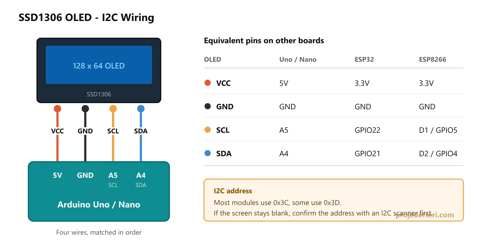
I2C needs four wires: VCC, GND and the two data lines (SDA, SCL). Which pins carry the data lines depends on the board.
| Board | SDA | SCL | VCC |
|---|---|---|---|
| Arduino Uno / Nano | A4 | A5 | 5V |
| Arduino Mega 2560 | 20 | 21 | 5V |
| Arduino Leonardo / Micro | 2 | 3 | 5V |
| ESP32 (default) | GPIO21 | GPIO22 | 3.3V |
| ESP8266 / NodeMCU | D2 (GPIO4) | D1 (GPIO5) | 3.3V |
| Raspberry Pi Pico | GP4 | GP5 | 3.3V |
Most modules carry an onboard regulator and level shifter, so they tolerate both 5V and 3.3V. Still, feed them your board’s own logic voltage: do not put 5V on an ESP32.
Find the I2C Address
SSD1306 modules use one of two addresses: 0x3C (very common) or 0x3D. The wrong address gives you a blank screen with no error at all. Scan instead of guessing:
#include <Wire.h>

void setup() {
  Wire.begin();
  Serial.begin(9600);
  while (!Serial);
  Serial.println("Scanning I2C...");

  byte found = 0;
  for (byte address = 1; address < 127; address++) {
    Wire.beginTransmission(address);
    if (Wire.endTransmission() == 0) {
      Serial.print("Device found at 0x");
      if (address < 16) Serial.print("0");
      Serial.println(address, HEX);
      found++;
    }
  }
  if (found == 0) Serial.println("Nothing found. Check the wiring.");
}

void loop() {}
Open the serial monitor at 9600 baud. If you see 0x3C you are ready. If you see nothing, the problem is the wiring, not the code.
Adafruit or U8g2?
There are two real options and both are good. The trade-off is RAM against convenience.
| Feature | Adafruit SSD1306 + GFX | U8g2 |
|---|---|---|
| RAM (128x64, full buffer) | 1024 bytes | 1024 bytes (F mode) or 128 bytes (1 mode) |
| Font choice | Small, GFX fonts | Very large, hundreds of fonts |
| Learning curve | Gentler, more examples | A bit steeper |
| Panels supported | The Adafruit ecosystem | Nearly every monochrome panel |
If you are on an Arduino Uno this line matters: the Uno has 2048 bytes of SRAM in total. A 128x64 full buffer eats half of it. U8g2’s page mode (U8G2_..._1_HW_I2C) drops the buffer to 128 bytes at the cost of repeating the drawing a few times. That is the fix when you run out of RAM.
Install from the Arduino IDE under Tools > Manage Libraries: Adafruit SSD1306 plus Adafruit GFX Library for one route, U8g2 for the other.
First Sketch: Text on Screen
The smallest working example with the Adafruit library:
#include <Wire.h>
#include <Adafruit_GFX.h>
#include <Adafruit_SSD1306.h>

#define WIDTH 128
#define HEIGHT 64
#define OLED_RESET -1        // I2C modules have no reset pin
#define OLED_ADDR 0x3C

Adafruit_SSD1306 display(WIDTH, HEIGHT, &Wire, OLED_RESET);

void setup() {
  Serial.begin(9600);

  if (!display.begin(SSD1306_SWITCHCAPVCC, OLED_ADDR)) {
    Serial.println("SSD1306 init failed");
    for (;;);           // stuck here means wrong address or bad wiring
  }

  display.clearDisplay();
  display.setTextSize(1);
  display.setTextColor(SSD1306_WHITE);
  display.setCursor(0, 0);
  display.println("Hello OLED");
  display.setTextSize(2);
  display.setCursor(0, 20);
  display.println("23.4 C");
  display.display();      // nothing appears without this line
}

void loop() {}
Three things to notice:
- Nothing reaches the panel until you call
display.display(). Every draw call only touches the buffer in RAM. setTextSize(1)uses the built in 6x8 font, so a 128x64 screen holds 8 lines of 21 characters.setTextSize(2)doubles every pixel with no smoothing.setCursor(x, y)sets the top left corner of the text. This differs from U8g2, where y is the baseline.
Drawing Shapes
On a monochrome panel the Adafruit GFX drawing calls take SSD1306_WHITE (turn the pixel on) and SSD1306_BLACK (turn it off).
display.clearDisplay();

display.drawPixel(10, 10, SSD1306_WHITE);
display.drawLine(0, 0, 127, 63, SSD1306_WHITE);
display.drawRect(4, 4, 60, 30, SSD1306_WHITE);      // outline only
display.fillRect(70, 4, 50, 30, SSD1306_WHITE);     // filled
display.drawRoundRect(4, 40, 60, 20, 5, SSD1306_WHITE);
display.drawCircle(100, 48, 12, SSD1306_WHITE);
display.fillTriangle(0, 63, 20, 40, 40, 63, SSD1306_WHITE);

display.display();
The origin is the top left corner: x grows to the right, y grows downward. On a 128x64 panel the valid range is 0-127 for x and 0-63 for y. Drawing outside that is not an error, it is silently clipped.
To rotate the screen, call display.setRotation(0..3). Each step is 90 degrees and swaps width with height.
Bitmaps and Logos
To show your own artwork you first need it as a C array. You can do that in the browser:
Then drop the array straight in:
const unsigned char logo [] PROGMEM = {
  // paste the image2cpp output here
};

display.clearDisplay();
display.drawBitmap(0, 0, logo, 128, 64, SSD1306_WHITE);
display.display();
PROGMEM keeps the array in flash instead of RAM. A 128x64 bitmap is 1024 bytes; on the Uno’s 2 KB of RAM there is no room to hold that a second time next to the buffer, so PROGMEM is mandatory rather than optional.
Animation
Animation is just the three step loop repeated quickly: clear, draw, send.
int x = 0;
int dir = 2;

void loop() {
  display.clearDisplay();

  display.fillCircle(x, 32, 8, SSD1306_WHITE);
  display.drawRect(0, 0, 128, 64, SSD1306_WHITE);

  display.display();

  x += dir;
  if (x >= 120 || x <= 8) dir = -dir;

  delay(20);
}
Scrolling text works the same way, x just marches negative:
const char* message = "Scrolling text example - Proje Defteri";
int offset = 128;

void loop() {
  display.clearDisplay();
  display.setTextSize(1);
  display.setTextColor(SSD1306_WHITE);
  display.setCursor(offset, 28);
  display.print(message);
  display.display();

  offset -= 2;
  if (offset < -((int)strlen(message) * 6)) offset = 128;
  delay(30);
}
Wire.setClock(400000); after display.begin() to run the bus at 400 kHz; most modules handle it without complaint and the frame rate jumps noticeably.For a real multi frame animation, store each frame as its own bitmap array and draw them in sequence. Remember that each frame costs 1024 bytes of flash: on the Uno’s 32 KB, leaving room for the rest of your program, you will struggle past 20 frames.
The Same Thing in U8g2
If you want more fonts or less RAM, the U8g2 side looks like this:
#include <U8g2lib.h>
#include <Wire.h>

// F = full buffer (1024 bytes of RAM), fast
U8G2_SSD1306_128X64_NONAME_F_HW_I2C u8g2(U8G2_R0, U8X8_PIN_NONE);

void setup() {
  u8g2.begin();
}

void loop() {
  u8g2.clearBuffer();
  u8g2.setFont(u8g2_font_6x10_tr);
  u8g2.drawStr(0, 10, "Temperature");
  u8g2.setFont(u8g2_font_logisoso24_tn);
  u8g2.drawStr(0, 50, "23.4");
  u8g2.sendBuffer();
  delay(1000);
}
When RAM is tight, swap _F_ for _1_ and move to the firstPage() / nextPage() loop:
U8G2_SSD1306_128X64_NONAME_1_HW_I2C u8g2(U8G2_R0, U8X8_PIN_NONE);

u8g2.firstPage();
do {
  u8g2.setFont(u8g2_font_6x10_tr);
  u8g2.drawStr(0, 10, "Low RAM mode");
} while (u8g2.nextPage());
In U8g2 the y argument of drawStr is the baseline, not the top edge. If you are coming from the Adafruit library, that is why your first line of text disappears off the top.
The SH1106 Difference
The SH1106 controller is nearly identical to the SSD1306 but its internal RAM is 132 pixels wide. A 128 pixel panel sits in the middle of that space. Run SSD1306 code on an SH1106 and the image shifts 2 pixels to the right with a thin strip of garbage down the right edge.
The fix is picking the right driver:
// on the U8g2 side only the class name changes
U8G2_SH1106_128X64_NONAME_F_HW_I2C u8g2(U8G2_R0, U8X8_PIN_NONE);
On the Adafruit side you need a separate library: Adafruit_SH110X.
Common Problems
The screen is completely blank
Work through it in order: does the I2C scanner see the device (if not, it is the wiring), is the address in begin() correct, and is there a display.display() at the end. If all three check out, measure the module’s supply.
The screen lights up but shows random pixels
Almost always display.begin() failed and the sketch carried on anyway. Check the return value the way the example above does.
The image is shifted 2 pixels with garbage on the right
You are driving an SH1106 panel with the SSD1306 driver. See the section above.
Text disappears off the top of the screen
In U8g2 the y argument of drawStr is the baseline; pass a y smaller than the font height and the text runs off the top. Start with drawStr(0, 10, ...).
The sketch crashes or behaves oddly on an Uno
You are out of RAM. A 128x64 full buffer is 1024 bytes and the Uno has 2048 in total. Long String objects, big arrays and literal text inside Serial.print eat what is left fast. Wrap fixed strings in F("...") and try U8g2’s page mode.
Accented characters come out wrong
The default Adafruit GFX font is plain ASCII. In U8g2, a font ending in _tf (such as u8g2_font_6x13_tf) covers Latin-1. For anything beyond that you need to compile a custom font or draw those characters as bitmaps.
Frequently Asked Questions
Does the SSD1306 work at 3.3V? Yes. Most modules have an onboard regulator and run from either 3.3V or 5V. Feed 3.3V on an ESP32 or ESP8266.
Can I connect two OLEDs at once? Over I2C yes, but they need different addresses. Some modules have a solder bridge on the back that switches between 0x3C and 0x3D. Without one you need separate I2C buses or an I2C multiplexer such as the TCA9548A.
What frame rate can I reach? At 100 kHz I2C the theoretical ceiling is 100 fps, realistically 30 to 50. Push the bus to 400 kHz and you can go above 100.
Do OLED panels suffer burn-in? Yes. OLED pixels dim with use. In a project that shows one static screen all day, shifting the content by a few pixels periodically, or clearing the display when idle, extends its life.
Should I get a colour OLED instead? Colour versions exist (SSD1331, SSD1351) but they use 2 bytes per pixel, so 128x64 needs a 16 KB buffer. That does not fit on an Uno. For colour work an ESP32 with a TFT panel (ST7735, ILI9341) makes more sense; you can work out the colour values with our RGB565 Color Converter.
Related Tools and Reading
- image2cpp - turn an image into an OLED bitmap array
- U8g2 Font List - pick a font and check whether the text fits
- Arduino Pinout and ESP32 Pinout - find the I2C pins
- I2C and the 16x2 LCD - the character LCD side