- The Cheap Yellow Display is the ESP32-2432S028R: an ESP32-WROOM-32 soldered onto a yellow PCB with a 2.8" 240x320 touch screen, microSD slot, RGB LED and light sensor, for roughly the price of a bare dev board plus a screen.
- Two revisions ship under the same model number. The 1x USB board uses an ILI9341, the 2x USB (CYD2USB) board uses an ST7789 and needs its colours inverted.
- The screen, the touch panel and the SD card each take their own SPI pins, so almost every GPIO is already spoken for.
- You get four usable pins: IO22, IO27, input-only IO35, and IO21 if you are willing to give up backlight control.
- Board setting in Arduino IDE is plain ESP32 Dev Module. The whole setup lives in
User_Setup.h, not in your sketch. - A white screen almost always means the wrong driver define, not a dead board.
Buying an ESP32, a 2.8" TFT, a touch controller and an SD slot separately costs more than this entire board, and you still have to wire it. That is the whole reason the Cheap Yellow Display became the default “I want a screen on my ESP32” answer.
The catch is that everything is pre-wired, which means the pin choices were made for you, some of them badly. This guide covers the pinout, how to tell your revision apart, the exact User_Setup.h that makes the screen work, and the handful of failures everyone hits on day one. 👇🏻
ESP32 CYD Pinout
If this is what you came for, here it is first:
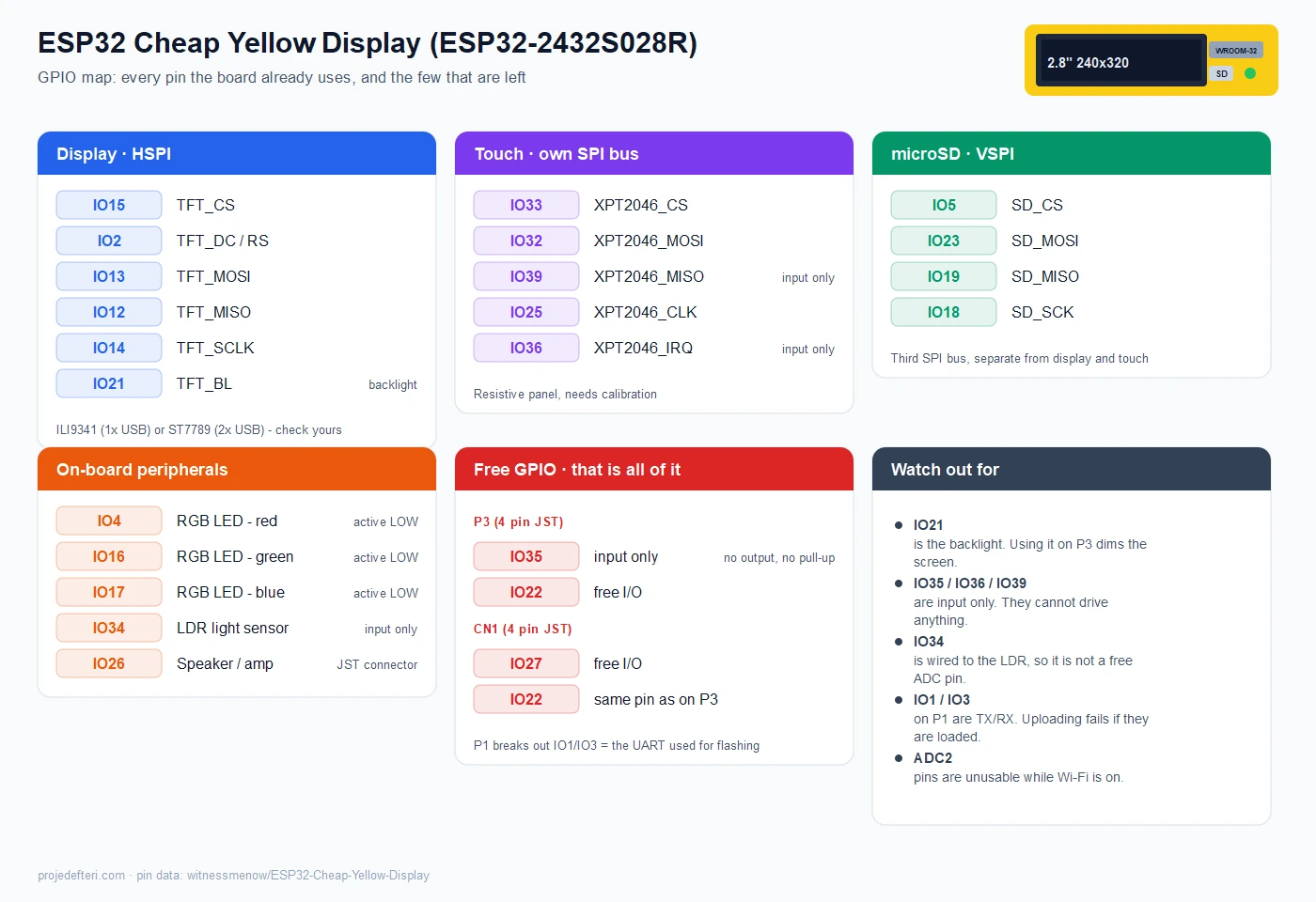
Tap the image to enlarge it on mobile. The short version: the board uses 20 of the ESP32’s GPIO before you write a single line of code.
| Bus | Pins |
|---|---|
| Display (HSPI) | IO15 CS, IO2 DC, IO13 MOSI, IO12 MISO, IO14 SCLK, IO21 backlight |
| Touch (XPT2046) | IO33 CS, IO32 MOSI, IO39 MISO, IO25 CLK, IO36 IRQ |
| microSD (VSPI) | IO5 CS, IO23 MOSI, IO19 MISO, IO18 SCK |
| On-board | IO4 red, IO16 green, IO17 blue, IO34 LDR, IO26 speaker |
| Broken out | IO35 (input only), IO22, IO27, and IO1/IO3 on P1 |
The ESP32 has two usable hardware SPI buses and the CYD needs three. The display takes HSPI, the SD card takes VSPI, and touch is driven separately on its own pins. That is why touch code on this board always looks a little odd compared to a normal SPI peripheral.
Which CYD Do You Have?
This is the single biggest source of “my screen is white” posts. Two boards ship as the ESP32-2432S028R, and the difference is visible from across the room: count the USB ports.
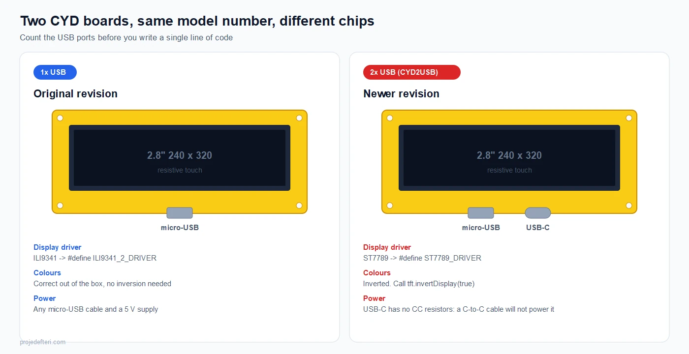
One micro-USB port means the original revision with an ILI9341. Colours are correct as they come.
A micro-USB and a USB-C port means the newer CYD2USB revision with an ST7789. Two things change: you need the ST7789 driver define, and the panel is inverted, so you have to call tft.invertDisplay(true). There is also a hardware trap here. That USB-C port has no CC resistors, so a USB-C to USB-C cable will not power the board at all. Use an A-to-C cable, or the micro-USB port.
If your screen stays white and you have already checked the cable, the driver define is almost certainly wrong for your revision.
What Is Actually On The Board
| Feature | Detail |
|---|---|
| MCU | ESP32-WROOM-32, dual core Xtensa LX6 at 240 MHz |
| Flash | 4 MB |
| PSRAM | None |
| Display | 2.8" TFT, 240 x 320, ILI9341 or ST7789 |
| Touch | XPT2046, resistive (needs a fingernail or stylus, and calibration) |
| Storage | microSD slot on its own SPI bus |
| Extras | RGB LED, LDR light sensor, speaker connector, CH340 USB-UART |
| Connectors | P1, P3, CN1 (4-pin JST) |
| Power | 5 V over USB |
Two of these deserve emphasis. There is no PSRAM, so a full-screen 16-bit frame buffer (240 x 320 x 2 = 150 KB) does not fit comfortably in RAM. LVGL on this board runs with partial buffers, not a full one. And the touch panel is resistive, not capacitive: it will not respond to a light fingertip the way a phone does, and it will need calibrating.
The Free GPIO Problem
This is the honest limitation of the CYD, and it is worth knowing before you design a project around it.
P3 breaks out GND, IO35, IO22 and IO21. CN1 breaks out GND, IO22, IO27 and 3.3 V. P1 breaks out VIN, IO1, IO3 and GND.
That gives you:
- IO22 and IO27 as genuinely free I/O. IO22 appears on both P3 and CN1, but it is the same single pin, not two.
- IO35 as input only. It cannot drive anything and has no internal pull-up.
- IO21 only if you accept losing backlight control.
- IO1 and IO3 are the UART used for flashing. Anything you hang on them can stop uploads from working.
So: two free pins, plus one input. If your project needs a temperature sensor and a relay, fine. If it needs six things, buy a different board or put an I2C expander on IO22 and IO27.
One more trap worth stating plainly: IO34 is not a free ADC pin. It is wired to the on-board light sensor, so reading it gives you room brightness, not whatever you connected.
Power, Battery and Cases
There is no charging circuit on the board. The CYD expects 5 V and normally takes it from USB; there is no TP4056 and no LiPo connector anywhere on it. So “how do I put a battery on a CYD” is a small hardware addition, not a setting.
The route the community takes: wire the LiPo cell to a TP4056 charging module, run its output through a 5 V boost converter, and feed the result to the VIN and GND pins on the P1 connector. P1 also carries IO1/IO3, the flashing UART, so leave those two alone while you solder.
Two warnings:
- The connectors are 1.25 mm pitch (most sellers say JST; the correct name is Molex PicoBlade). Standard 2.54 mm jumper wires do not fit, so buy a pre-made cable.
- On the USB-C CYD2USB revision the C port has no CC resistors. A C-to-C cable will not power the board at all; use an A-to-C cable.
For enclosures there is nothing official, but Printables and Thingiverse carry plenty of 3D printed cases made for this exact board, including desk stands, wall panels and versions with a battery compartment. Searching for ESP32-2432S028R returns better matches than searching for CYD.
Arduino IDE Setup
Install the ESP32 boards package, then select Tools > Board > ESP32 Arduino > ESP32 Dev Module. Leave the defaults; flash size 4 MB, partition scheme Default. There is no special CYD board entry, and you do not need one.
The screen is configured entirely inside the TFT_eSPI library, in its User_Setup.h file. This trips people up because editing a library file feels wrong, but that is how TFT_eSPI works.
Install TFT_eSPI from the Library Manager, then open Documents/Arduino/libraries/TFT_eSPI/User_Setup.h and replace its contents with:
// --- ESP32 Cheap Yellow Display (ESP32-2432S028R) ---

// 1x USB board:
#define ILI9341_2_DRIVER
// 2x USB (CYD2USB) board: comment the line above and use this instead
// #define ST7789_DRIVER

#define TFT_WIDTH  240
#define TFT_HEIGHT 320

#define TFT_MISO 12
#define TFT_MOSI 13
#define TFT_SCLK 14
#define TFT_CS   15
#define TFT_DC    2
#define TFT_RST  -1

#define TFT_BL   21
#define TFT_BACKLIGHT_ON HIGH

#define LOAD_GLCD
#define LOAD_FONT2
#define LOAD_FONT4
#define LOAD_FONT6
#define LOAD_FONT7
#define LOAD_FONT8
#define LOAD_GFXFF
#define SMOOTH_FONT

#define SPI_FREQUENCY       55000000
#define SPI_READ_FREQUENCY  20000000
#define SPI_TOUCH_FREQUENCY  2500000

#define USE_HSPI_PORT
USE_HSPI_PORT is not optional. Without it TFT_eSPI grabs VSPI and collides with the SD card.
First sketch
#include <TFT_eSPI.h>

TFT_eSPI tft = TFT_eSPI();

void setup() {
  pinMode(TFT_BL, OUTPUT);
  digitalWrite(TFT_BL, HIGH);   // backlight on

  tft.init();
  tft.setRotation(1);           // 1 = landscape
  // tft.invertDisplay(true);   // uncomment on the 2x USB / ST7789 board

  tft.fillScreen(TFT_BLACK);
  tft.setTextColor(TFT_YELLOW, TFT_BLACK);
  tft.setTextSize(2);
  tft.setCursor(20, 20);
  tft.println("Hello CYD");
}

void loop() {}
If you get a backlight but no image, the driver define is wrong. If you get an image with wrong colours, you are on the ST7789 board and need invertDisplay(true).
Touch
Touch uses the XPT2046 on its own pins, so you hand it a separate SPI instance instead of the default one. Install XPT2046_Touchscreen, then:
#include <SPI.h>
#include <XPT2046_Touchscreen.h>

#define XPT2046_IRQ  36
#define XPT2046_MOSI 32
#define XPT2046_MISO 39
#define XPT2046_CLK  25
#define XPT2046_CS   33

SPIClass touchSpi = SPIClass(VSPI);
XPT2046_Touchscreen ts(XPT2046_CS, XPT2046_IRQ);

void setup() {
  Serial.begin(115200);
  touchSpi.begin(XPT2046_CLK, XPT2046_MISO, XPT2046_MOSI, XPT2046_CS);
  ts.begin(touchSpi);
  ts.setRotation(1);
}

void loop() {
  if (ts.tirqTouched() && ts.touched()) {
    TS_Point p = ts.getPoint();
    // raw values, roughly 200..3700 on both axes
    int x = map(p.x, 200, 3700, 0, 320);
    int y = map(p.y, 240, 3800, 0, 240);
    Serial.printf("raw %d,%d  ->  screen %d,%d\n", p.x, p.y, x, y);
    delay(100);
  }
}
Those map() limits are a starting point, not gospel. Every panel differs. Print the raw values, touch each corner, write down what you actually get, and put your own numbers in. This is the calibration step, and skipping it is why touch feels offset for so many people.
Note that both touch and the SD card want the VSPI peripheral, with different pins. Using them in the same sketch works, but you have to re-begin the bus when you switch between them.
SD Card, RGB LED and Light Sensor
The SD slot sits on VSPI with a non-default CS pin:
#include <SPI.h>
#include <SD.h>

#define SD_CS 5

SPIClass sdSpi = SPIClass(VSPI);

void setup() {
  Serial.begin(115200);
  sdSpi.begin(18, 19, 23, SD_CS);   // SCK, MISO, MOSI, CS
  if (!SD.begin(SD_CS, sdSpi)) {
    Serial.println("SD mount failed");
    return;
  }
  Serial.printf("Card size: %llu MB\n", SD.cardSize() / (1024 * 1024));
}

void loop() {}
The RGB LED is active LOW, which surprises everyone once:
#define LED_RED   4
#define LED_GREEN 16
#define LED_BLUE  17

void setup() {
  pinMode(LED_RED, OUTPUT);
  pinMode(LED_GREEN, OUTPUT);
  pinMode(LED_BLUE, OUTPUT);
  digitalWrite(LED_RED, LOW);      // LOW turns it ON
  digitalWrite(LED_GREEN, HIGH);   // HIGH turns it OFF
  digitalWrite(LED_BLUE, HIGH);
}
And the light sensor is a plain analog read on IO34, useful for dimming the backlight automatically:
int light = analogRead(34); // 0..4095, higher means darker on most units
Common Problems
| Symptom | Cause |
|---|---|
| White screen, backlight on | Wrong driver define. ILI9341 on 1x USB, ST7789 on 2x USB |
| Colours inverted | ST7789 board without tft.invertDisplay(true) |
| Nothing at all on USB-C | C-to-C cable. That port has no CC resistors, use A-to-C |
| Display works, SD does not | USE_HSPI_PORT missing from User_Setup.h |
| Touch registers in the wrong place | Calibration values not set for your panel |
| Touch does not respond to a fingertip | It is a resistive panel, press harder or use a stylus |
| Upload fails | Something connected to IO1/IO3 on P1, or hold BOOT while it connects |
| Text looks squashed | Wrong setRotation(), 0/2 are portrait, 1/3 landscape |
What To Build With It
The autocomplete for this board tells you what people actually do with it: Home Assistant dashboards, desk clocks and alarms, weather panels, flight trackers, internet radios, stream deck style shortcut panels for a PC, and small control UIs. All of those are the same shape, which is a Wi-Fi device that fetches a value and draws it big.
If you would rather start without writing code, there is a shortcut. The community maintains launcher style builds that flash a menu of example apps onto the board in one go; most install through a browser-based web flasher, after which you pick an app on the screen. It is a fast way to see what the board can do, though for anything permanent your own sketch is cleaner.
The board runs ESPHome and LVGL happily, with the PSRAM caveat above. If you are hand-rolling the UI in TFT_eSPI instead, two of our tools save the tedious part:
- LVGL Image Converter turns a PNG into an LVGL C array
- RGB565 Color Converter gives you the 16-bit colour values TFT_eSPI expects
- LCD Assistant / image2cpp converts bitmaps for
pushImage()
Where the CYD stops making sense is anything sensor-heavy. Two free pins is two free pins. For that, an ESP32-S3 board with a separate display is the better shape, and you can compare boards in the ESP32 pinout tool.
Is It Worth Buying?
Yes, with a clear head about what it is. It is the cheapest way to get a working touch screen on an ESP32 with zero wiring, and the community documentation is unusually good for a no-name board. It is not a general purpose dev board, the touch is resistive, and you cannot expand it much.
Buy it if the screen is the project. Skip it if the screen is one part of a bigger build.
Frequently Asked Questions
What does CYD stand for? Cheap Yellow Display. It is a community nickname for the ESP32-2432S028R, named after the yellow PCB. The manufacturer does not use the term.
Which display driver does the CYD use? ILI9341 on the single micro-USB revision, ST7789 on the newer CYD2USB revision with micro-USB and USB-C. Count the USB ports to tell them apart.
How many free GPIO pins does the CYD have? Two usable I/O pins (IO22, IO27) and one input-only pin (IO35), plus IO21 if you give up backlight control.
Does the CYD have PSRAM? No. It has 4 MB of flash and no PSRAM, so a full-screen frame buffer will not fit in RAM. LVGL runs with partial buffers.
Why is my CYD screen white? Almost always the wrong driver define in TFT_eSPI’s User_Setup.h for your board revision. Check the USB ports, then set ILI9341_2_DRIVER or ST7789_DRIVER accordingly.
Which board do I select in Arduino IDE for the CYD? ESP32 Dev Module, with the default flash and partition settings. There is no dedicated CYD entry.
Can the CYD run Home Assistant dashboards? Yes. It works with ESPHome and with LVGL-based dashboard firmware, and it is one of the most common uses for the board.
Why does my USB-C cable not power the board? The USB-C port on the CYD2USB revision has no CC resistors, so a C-to-C cable delivers nothing. Use a USB-A to USB-C cable or the micro-USB port.
Can I run the CYD on a battery? Not directly. The board has no charging circuit, so a LiPo cell cannot be connected as-is. The usual fix is a TP4056 charging module plus a 5 V boost converter, feeding VIN and GND on the P1 connector. The connectors are 1.25 mm pitch, so buy a pre-made cable rather than trying jumper wires.
Is the CYD touch screen capacitive? Not on this model. The ESP32-2432S028R uses a resistive panel driven by an XPT2046, which needs a fingernail or stylus and a calibration pass. Other CYD boards with capacitive touch exist under different model numbers, but their pinout and driver settings differ from this guide.