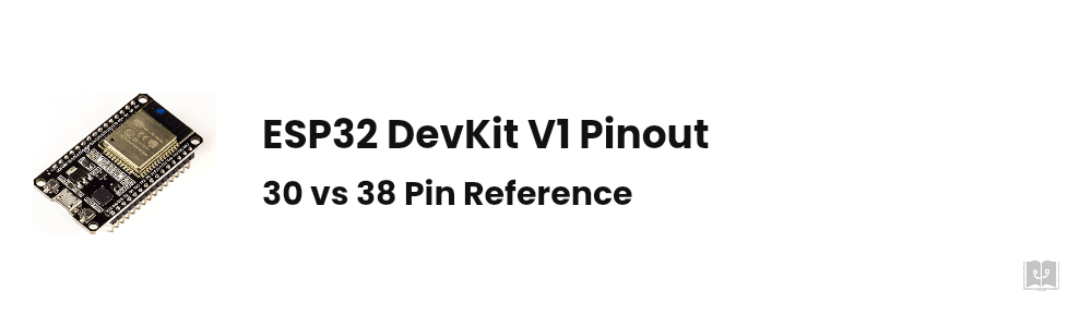
- The ESP32 is Espressif’s dual-core Xtensa LX6 MCU running at up to 240 MHz with Wi-Fi and Bluetooth. The chip has 34 GPIOs; boards break out either 30 or 38 pins.
- The 30 vs 38 pin difference is not just pin count: six of the extra pins on the 38-pin board are wired to the internal flash and cannot be used.
- GPIO6 through GPIO11 belong to the flash chip. Connect anything there and the board will not boot.
- GPIO34, 35, 36 and 39 are input only. They cannot drive an output and have no internal pull-up or pull-down.
- GPIO0, 2, 5, 12 and 15 are strapping pins. Hold one at the wrong level during boot and the board either refuses to start or hangs in flashing mode.
- ADC2 does not work while Wi-Fi is on. Wire analog sensors to the ADC1 pins, GPIO32 to GPIO39.
- The board runs on 3.3 V logic and is not 5 V tolerant. Never wire a 5 V sensor output straight to a GPIO.
The ESP32 is cheap, fast, and ships with Wi-Fi and Bluetooth built in. It also has one habit that drives beginners up the wall: the board says 38 pins, and you cannot use all of them. Wire a relay to one pin and the board stops booting. Wire a sensor to another and the reading turns to noise the moment Wi-Fi comes up. Wire an LED to a third and it flickers once on every reset.
None of that is a faulty board. Every one of those behaviours is written into the pin map. This guide walks through the DevKit V1 pinout, which pins you genuinely cannot use and why, the real difference between the 30 and 38 pin boards, and the traps waiting for you when you flash your first sketch. 👇🏻
ESP32 Pinout Diagram
This is what most people came for, so it goes first. The table below lists every pin broken out on an ESP32 DevKit V1 (ESP32-WROOM-32) board along with its secondary functions:
| Pin | ADC | Touch | RTC | Other function | Note |
|---|---|---|---|---|---|
| GPIO0 | ADC2_CH1 | T1 | ✔ | BOOT button | Strapping, internal pull-up |
| GPIO1 | UART0 TX | Prints the boot log | |||
| GPIO2 | ADC2_CH2 | T2 | ✔ | On-board blue LED | Strapping |
| GPIO3 | UART0 RX | HIGH at boot | |||
| GPIO4 | ADC2_CH0 | T0 | ✔ | Free | |
| GPIO5 | VSPI CS | Strapping, outputs PWM at boot | |||
| GPIO6-11 | Internal flash | Unusable | |||
| GPIO12 | ADC2_CH5 | T5 | ✔ | MTDI (JTAG) | Strapping, HIGH at boot stops the board |
| GPIO13 | ADC2_CH4 | T4 | ✔ | MTCK (JTAG) | Free |
| GPIO14 | ADC2_CH6 | T6 | ✔ | MTMS (JTAG) | Outputs PWM at boot |
| GPIO15 | ADC2_CH3 | T3 | ✔ | MTDO (JTAG) | Strapping, LOW silences the boot log |
| GPIO16 | UART2 RX | Reserved for PSRAM on WROVER modules | |||
| GPIO17 | UART2 TX | Reserved for PSRAM on WROVER modules | |||
| GPIO18 | VSPI CLK | Free | |||
| GPIO19 | VSPI MISO | Free | |||
| GPIO21 | I2C SDA | Default I2C data line | |||
| GPIO22 | I2C SCL | Default I2C clock line | |||
| GPIO23 | VSPI MOSI | Free | |||
| GPIO25 | ADC2_CH8 | ✔ | DAC1 | True analog output | |
| GPIO26 | ADC2_CH9 | ✔ | DAC2 | True analog output | |
| GPIO27 | ADC2_CH7 | T7 | ✔ | Free | |
| GPIO32 | ADC1_CH4 | T9 | ✔ | Analog that survives Wi-Fi | |
| GPIO33 | ADC1_CH5 | T8 | ✔ | Analog that survives Wi-Fi | |
| GPIO34 | ADC1_CH6 | ✔ | Input only | ||
| GPIO35 | ADC1_CH7 | ✔ | Input only | ||
| GPIO36 (VP) | ADC1_CH0 | ✔ | Input only | ||
| GPIO39 (VN) | ADC1_CH3 | ✔ | Input only |
There is no GPIO20, GPIO24 or GPIO28-31 on the board. Those pads are not bonded out of the package, so stop looking for them. GPIO37 and GPIO38 exist on the die but are not routed to the header on DevKit boards.
👉🏻 To see the pins laid out on the board itself, our ESP32 pinout tool shows DevKit V1 next to the S3, C3, C6 and S2 boards, and clicking a pin expands its functions.
What Is the ESP32?
The ESP32 is the Wi-Fi and Bluetooth MCU Espressif released in 2016 as the successor to the ESP8266. The overwhelming majority of boards on the market use the same module: ESP32-WROOM-32.
| Spec | Value |
|---|---|
| CPU | 32-bit Xtensa LX6, dual core, up to 240 MHz |
| SRAM | 520 KB |
| Flash | 4 MB on the module (WROOM-32) |
| Wireless | Wi-Fi 802.11 b/g/n 2.4 GHz + Bluetooth 4.2 Classic and LE |
| GPIO | 34 on the chip (25 to 30 usable on a board) |
| ADC | 2x 12-bit, 18 channels total |
| DAC | 2x 8-bit |
| Touch | 10 channels |
| Interfaces | 3x UART, 2x I2C, 4x SPI, 2x I2S, CAN, Ethernet MAC, SD/MMC |
| PWM | 16 LEDC channels, routable to any output pin |
| Deep sleep | ~10 µA, with a ULP coprocessor |
Next to an Arduino Uno the gap is absurd: the Uno gives you 16 MHz on one core and 2 KB of RAM, the ESP32 gives you 240 MHz on two cores and 520 KB, with radios in the box. What you give up is 5 V tolerance and the Uno’s “any pin does anything” freedom.
The ESP8266 (NodeMCU) is still sold and still cheaper. Single core, no Bluetooth, 17 GPIOs and a single ADC channel.
If the job is reading one sensor and pushing it to a server, the ESP8266 is enough. If you need Bluetooth, several analog sensors, touch input or a display, get the ESP32. The price gap is small these days.
To start with the ESP8266 instead, see our NodeMCU setup guide.
30 Pin vs 38 Pin
Two boards ship under the same name, and the difference is not simply size.
30-pin DevKit V1: 15 pins per side. Every usable GPIO is broken out.
38-pin DevKit V1: 19 pins per side. Six of the eight extra pins are the data lines of the internal flash chip (GPIO6, 7, 8, 9, 10, 11). The remaining two are an extra ground and a power pin.
So the 38-pin board does not hand you eight extra pins. It hands you two, plus six traps. They are on the header, you can solder to them, and the moment you connect anything the chip can no longer read its own flash and the board stops booting.
Those silkscreen labels, SD0, SD1, SD2, SD3, CMD, CLK, are exactly these pins. The names suggest you can hang an SD card off them. You cannot; the names come from the flash chip’s SPI bus.
Leave all six unconnected. For an SD card, use the regular SPI pins (GPIO18, 19, 23 and any free pin for CS).
So which one should you buy? The only practical differences are the extra ground pin and breadboard fit. A 38-pin board usually covers every free hole on a standard breadboard, forcing you to hang jumpers off the side. That makes the 30-pin board nicer to prototype with.
Pins You Cannot Use
This is the list that quietly breaks beginner projects. There are four groups.
1. Pins owned by the flash chip
GPIO6, 7, 8, 9, 10 and 11 are wired to the internal SPI flash. Espressif states it plainly: these pins are usually connected to the SPI flash and PSRAM integrated on the module and should not be used for other purposes.
On boards using a WROVER module, GPIO16 and GPIO17 are taken by PSRAM as well. On a plain WROOM-32 board those two are free and usable as UART2.
2. Input-only pins
GPIO34, GPIO35, GPIO36 (VP) and GPIO39 (VN) cannot drive an output. They also have no internal pull-up or pull-down resistors.
In practice: put a button on one of them and INPUT_PULLUP does nothing, so you need an external 10 kΩ resistor. Put an LED on one and it never lights.
These four are ideal for analog sensors, because all of them sit on ADC1.
Straight from Espressif’s notes: do not use interrupts on GPIO36 and GPIO39 when using the ADC, or when Wi-Fi and Bluetooth run with sleep mode enabled. A hardware issue causes spurious triggers.
Reading them with analogRead is fine.
3. Strapping pins
Five pins decide how the chip behaves the instant it powers up:
| Pin | Role | What goes wrong |
|---|---|---|
| GPIO0 | Flashing mode | LOW at boot means the board waits in bootloader mode instead of running your sketch |
| GPIO2 | Flashing mode helper | Must also be LOW while GPIO0 is LOW |
| GPIO5 | SDIO timing | Forcing it LOW at boot can break startup |
| GPIO12 | Flash voltage (MTDI) | HIGH at boot drops the flash rail to 1.8 V and the board never starts |
| GPIO15 | Boot log (MTDO) | LOW silences the startup output on the serial port |
The nastiest of the five is GPIO12. Connect a module that carries a 10 kΩ pull-up on that line (plenty of display and relay boards do) and the board goes dark, with nothing on the serial port to tell you why.
The rule is simple: do not connect anything that forces a level on those five pins during boot. Once the sketch is running they behave like ordinary GPIOs.
4. Pins that twitch at boot
These are not forbidden, just surprising:
- GPIO1 and GPIO3: the UART0 pair. They print the boot log and are busy whenever you use the serial monitor.
- GPIO5, GPIO14 and GPIO15: emit a brief PWM burst at startup.
Put a relay on one of those and it clicks on every reset. Put a motor driver there and the motor twitches. Keep critical loads off them.
The pins you can actually use
With Wi-Fi enabled, the serial port in use and a standard WROOM-32 board, what is left is:
Input and output: GPIO4, 13, 16, 17, 18, 19, 21, 22, 23, 25, 26, 27, 32, 33 Input only: GPIO34, 35, 36, 39
That is 18 usable pins on a board advertised as 38. For most projects it is plenty.
ADC, DAC and Touch Pins
ADC2 stops reading when Wi-Fi is on
The ESP32 has two separate analog-to-digital converters, and the second one shares hardware with the radio.
- ADC1: GPIO32, 33, 34, 35, 36, 39. Works fine with Wi-Fi running.
- ADC2: GPIO0, 2, 4, 12, 13, 14, 15, 25, 26, 27. Unavailable while the Wi-Fi driver is active.
Espressif’s documentation says it outright: ADC2 is also used by Wi-Fi, and the driver arbitrates between the two. On the Arduino side that translates into something less polite: call WiFi.begin() and every analogRead on an ADC2 pin returns 0 or garbage.
The rule: in any Wi-Fi project, analog sensors go on GPIO32 to GPIO39. Do not read analog anywhere else.
The ADC is not linear
The converter is 12-bit, so it returns 0 to 4095. At the default attenuation, however, readings near 0 V and above roughly 3.1 V drift away from linear. For accurate measurements, set the range with analogSetAttenuation() or use a divider to move your working range into the middle of the scale.
Our voltage divider calculator does the resistor maths for you.
DAC: real analog output
GPIO25 and GPIO26 are the only true analog outputs on the chip. They are 8-bit, so 0 to 255. Call dacWrite(25, 128) and the pin genuinely sits at 1.65 V.
That is enough for simple tone generation, an analog control signal or a reference voltage. For quality audio you want I2S and an external DAC module.
Touch pins
Ten pins sense capacitive touch: GPIO0, 2, 4, 12, 13, 14, 15, 27, 32 and 33. Solder a wire or a copper pad straight to one and read it with touchRead(); no extra circuitry needed.
Careful though: most of those are strapping or ADC2 pins as well. The cleanest pair for touch input is GPIO32 and GPIO33.
SPI, UART and PWM Pins
This is where people coming from an Arduino Uno get caught out: on the ESP32, most pins are not fixed.
The chip contains a GPIO matrix. On the Uno, the I2C hardware is physically bonded to A4 and A5 and that is that. On the ESP32 there is a routing layer between each peripheral and the pads, so you can assign nearly any function to nearly any pin.
Wire.begin(4, 5);                          // move I2C to GPIO4 and GPIO5
Serial2.begin(9600, SERIAL_8N1, 13, 27);   // move UART2 to GPIO13/27
The “default” pins in the table above are simply what the libraries pick when you pass no arguments. If a module hogs GPIO21, moving I2C elsewhere is a one-liner.
The exception: the ADC, DAC and touch blocks do not go through the matrix. Analog input only works on ADC pins and the DAC only on GPIO25 and GPIO26. That is physical silicon, not routing.
SPI
The chip has four SPI controllers, two of them reserved for flash. You get the other two:
| Controller | CLK | MISO | MOSI | CS |
|---|---|---|---|---|
| VSPI (default) | GPIO18 | GPIO19 | GPIO23 | GPIO5 |
| HSPI | GPIO14 | GPIO12 | GPIO13 | GPIO15 |
Calling SPI.begin() with no arguments gives you VSPI. Note that two of the HSPI pins (GPIO12 and GPIO15) are strapping pins, which is usually the culprit when an SD card or display module stops the board from booting.
UART
Three hardware serial ports:
- UART0 (GPIO1 TX, GPIO3 RX): tied to the USB bridge. This is
Serial. - UART2 (GPIO17 TX, GPIO16 RX): free to use as
Serial2. Perfect for a GPS module, an RFID reader or talking to another board. - UART1: its default pins land on the flash bus, so it has to be remapped through the matrix before use.
PWM
There is no separate group of “PWM pins” like on the Uno. Any output-capable pin can do PWM, because the 16 independent LEDC channels can be routed anywhere.
Version 3.x of the Arduino ESP32 core simplified the API:
ledcAttach(16, 5000, 8);   // GPIO16, 5 kHz, 8-bit resolution
ledcWrite(16, 128);        // 50% duty cycle
Code written against the old ledcSetup plus ledcAttachPin pair will not compile on 3.x. If an example you found online throws errors, check this first.
Deep Sleep and RTC Pins
On battery you will put the ESP32 into deep sleep, where it draws roughly 10 µA. While asleep almost the whole chip is powered down and only the RTC domain stays alive.
The consequence for wiring: if a button or sensor has to wake the board, that pin must be RTC-capable. Those are the pins marked ✔ in the RTC column above:
GPIO0, 2, 4, 12, 13, 14, 15, 25, 26, 27, 32, 33, 34, 35, 36, 39
GPIO16 to GPIO23 cannot wake the chip. Put your button on GPIO18, call esp_sleep_enable_ext0_wakeup(), and the sketch compiles cleanly but the board never wakes.
Any value that must survive sleep needs the RTC_DATA_ATTR marker as well, since ordinary variables are reinitialised:
RTC_DATA_ATTR int wakeCount = 0;
Common Wiring Examples
Reading a pin map is one thing, putting the sensor on the right pin is another. The three that come up most:
I2C LCD display: SDA to GPIO21, SCL to GPIO22, VCC to VIN (the module wants 5 V), GND to GND. Because the display runs on 5 V, the I2C lines sit at 5 V too; most modules tolerate this, but use a level shifter if you want to be safe. For the code side, see our I2C 16x2 LCD guide.
DHT11 / DHT22 temperature sensor: the data pin goes to any free GPIO, and GPIO4 is a comfortable choice. Power it from 3.3 V and stay off the strapping pins. Our DHT11 and DHT22 guide covers the code, and the DHT code generator writes the sketch for you.
HC-SR04 distance sensor: Trig can go to any output pin, but Echo drives 5 V and must not touch a GPIO directly. Put a divider in between: 1 kΩ from Echo to the GPIO, 2 kΩ from the GPIO to GND. Details in our HC-SR04 guide.
Power Pins and Electrical Limits
| Pin | Purpose |
|---|---|
| VIN / 5V | External 5 V input, feeds the on-board regulator |
| 3V3 | Regulator output, use this to power sensors |
| GND | Ground, several pins, all common |
| EN | Reset. Pulling it LOW halts the chip |
Three limits worth memorising:
- Logic is 3.3 V and the pins are not 5 V tolerant. Wire a 5 V sensor output (some ultrasonic and LCD modules) directly to a GPIO and you can damage it. Use a divider or a level shifter.
- Absolute maximum is 40 mA per pin, and you should design for 20 mA. Always use a resistor with an LED, and never drive a motor or relay coil straight off a pin.
- How much the 3V3 rail can supply depends on the regulator. On typical AMS1117 boards do not count on more than a few hundred milliamps, and remember the chip itself pulls close to 500 mA in bursts while transmitting.
If the serial monitor loops on Brownout detector was triggered, the problem is power, not code. The chip draws a current spike the moment the radio comes up and the rail sags.
Work through it in order: a short, decent USB cable; a proper 5 V supply instead of a front-panel USB port; a 100-470 µF capacitor across 3V3 and GND. The first one fixes most cases.
First Sketch in the Arduino IDE
1. Install the driver
There is a second chip on the board that talks to your computer, and it comes in two common flavours:
- CP2102 (Silicon Labs): a small square IC on the board. Driver from the Silicon Labs site.
- CH340 (WCH): common on cheaper clone boards.
If the board shows up with a yellow warning in Device Manager, the driver is missing. Windows 11 usually recognises the CP2102 on its own but not the CH340.
2. Add board support
If the Arduino IDE is not installed yet, start with our Arduino IDE download guide.
Under File → Preferences → Additional Board Manager URLs, add:
https://espressif.github.io/arduino-esp32/package_esp32_index.json
Then open Tools → Board → Boards Manager, search for “esp32” and install the Espressif Systems package.
3. Pick the board
Tools → Board → ESP32 Arduino → DOIT ESP32 DEVKIT V1. If your exact board is not listed, ESP32 Dev Module always works.
An upload speed of 921600 is fine on most boards. If uploads die halfway, drop to 115200.
4. Blink the on-board LED
On the DevKit V1 the blue LED sits on GPIO2:
#define LED_PIN 2

void setup() {
  Serial.begin(115200);
  pinMode(LED_PIN, OUTPUT);
  Serial.printf("Chip: %s, cores: %d, clock: %d MHz\n",
                ESP.getChipModel(), ESP.getChipCores(), getCpuFrequencyMhz());
  Serial.printf("Flash: %u MB\n", ESP.getFlashChipSize() / (1024 * 1024));
}

void loop() {
  digitalWrite(LED_PIN, HIGH);
  delay(500);
  digitalWrite(LED_PIN, LOW);
  delay(500);
}
If the serial monitor prints the chip model and flash size, the board is configured correctly.
5. When the upload fails
Failed to connect to ESP32: Timed out waiting for packet header is the classic. The fix lives on the board itself:
Hold the BOOT button, keep holding it for two or three seconds after the IDE prints “Connecting…”, then let go.
Some boards ship without the auto-reset circuit, so you will do this on every upload. Still stuck? Tap EN once, or hold BOOT while pressing EN, and close anything else holding the serial port open, the serial monitor included.
Wrapping Up
The ESP32 pin map looks intimidating at first, but it comes down to four rules. Learn these and the rest follows:
- GPIO6-11 belong to the flash chip, even on the 38-pin board. Leave them alone.
- GPIO34, 35, 36 and 39 are input only, with no internal pull resistors.
- GPIO0, 2, 5, 12 and 15 are strapping pins. Nothing may force a level on them at boot, GPIO12 above all.
- With Wi-Fi on, analog reads happen on GPIO32-39, because ADC2 is off limits.
If you need more pins, native USB or a camera interface, the next step up is the ESP32-S3. If a display is what you are after, our OLED SSD1306 guide and the image to C array converter will save you an afternoon.
👉🏻 Keep our ESP32 pinout tool open while you wire things up; it shows five boards side by side.