- ESP32-S3 is Espressif’s dual-core Xtensa LX7 MCU running at 240 MHz with Wi-Fi and Bluetooth 5 (LE). 45 GPIOs, 512 KB of SRAM.
- Three things set it apart from the classic ESP32: built-in USB OTG, 14 touch channels, and a vector instruction set for neural-network workloads.
- Codes like N8R8 and N16R8 on the board are not arbitrary: N = flash, R = PSRAM, numbers in megabytes.
- The board has two USB ports and they behave differently. This is where beginners get stuck.
- GPIO35, GPIO36 and GPIO37 are unusable on many variants, GPIO19 and GPIO20 belong to USB, and four pins do double duty as strapping pins.
- Depending on the board revision, the RGB LED sits on either GPIO48 or GPIO38. If your blink sketch does nothing, check that first.
If you have built something with an ESP32 and then tried to add a camera, audio, or a color display, you have probably hit the wall: not enough pins, not enough RAM, no USB.
ESP32-S3 exists for exactly that. This guide walks through the pinout, decodes the cryptic model codes printed on the board, lists the pins you genuinely cannot use, and covers the two traps that catch people flashing their first sketch. 👇🏻
ESP32-S3 Pinout Diagram
If this is what you came for, here it is up front. The diagram below is Espressif’s official pinout for the ESP32-S3-DevKitC-1, their own reference development board:
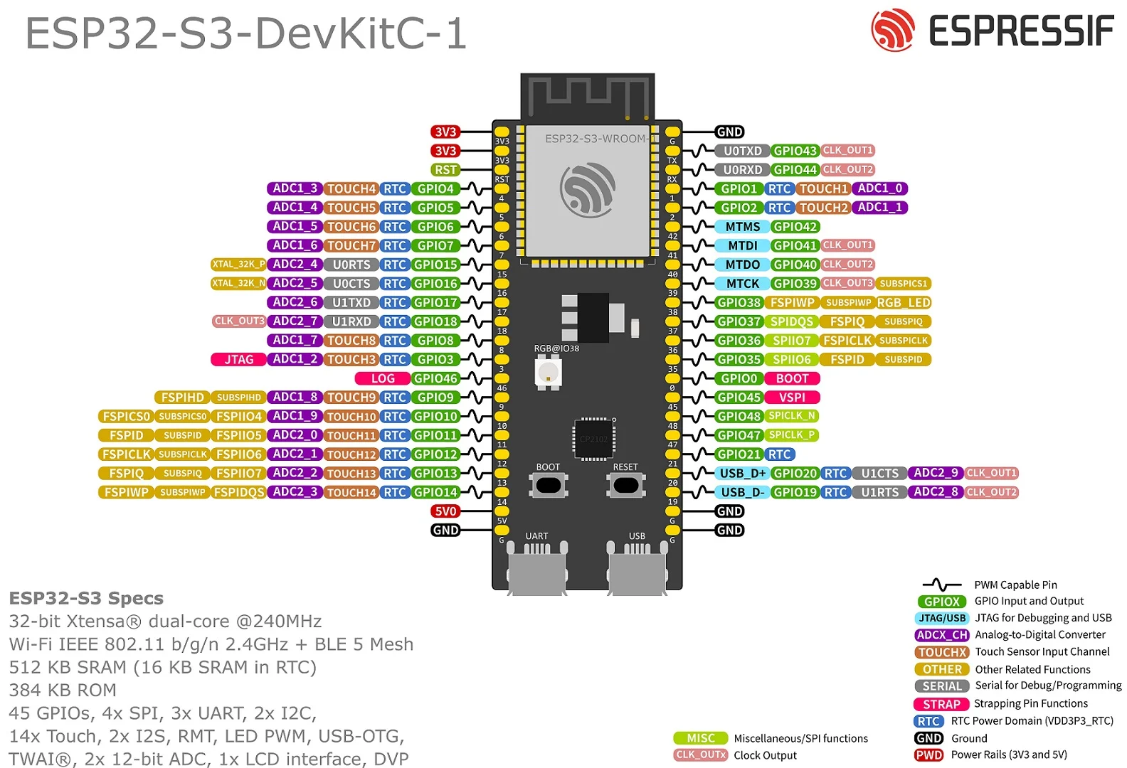
The image is small on mobile, so tap it to zoom. If you have a different board (Waveshare, XIAO, Super Mini), the physical pin order changes but what each GPIO number does stays the same, because those functions come from the chip, not the board.
If you are cross-referencing boards, our ESP32 pinout tool covers ESP32-S3-DevKitC-1, S3-WROOM-1, C3, C6 and S2 side by side.
What Is ESP32-S3?
ESP32-S3 is the Wi-Fi + Bluetooth microcontroller Espressif introduced in 2021 as the successor to the classic ESP32.
The official spec sheet:
| Feature | Value |
|---|---|
| CPU | 32-bit Xtensa LX7, dual core, 240 MHz |
| SRAM | 512 KB (16 KB of it in RTC) |
| ROM | 384 KB |
| Wireless | Wi-Fi 802.11 b/g/n 2.4 GHz + Bluetooth 5 (LE) |
| GPIO | 45 |
| Touch | 14 channels |
| ADC | 2x 12-bit |
| Interfaces | 4x SPI, 3x UART, 2x I2C, 2x I2S, RMT, LED PWM, TWAI, SD/MMC |
| Notable | USB-OTG, LCD interface, DVP camera interface, ULP core |
| AI | Vector instruction set (ESP-DSP and ESP-NN libraries) |
How is it different from the classic ESP32?
Here is the part that trips people up: ESP32-S3 is not strictly better than the classic ESP32. Things were added, and things were removed.
| Feature | ESP32 (classic) | ESP32-S3 |
|---|---|---|
| Core | Xtensa LX6 x2 | Xtensa LX7 x2 |
| SRAM | 520 KB | 512 KB |
| GPIO | 34 | 45 |
| Bluetooth | 4.2 Classic + LE | 5 (LE only) |
| USB | None, needs a bridge chip | Built-in USB-OTG |
| DAC | Yes (2 channels) | No |
| Ethernet MAC | Yes | No |
| Camera interface | No | DVP |
| Vector instructions | No | Yes |
What that means in practice:
- If you use Bluetooth Classic, do not move to the S3. The
BluetoothSeriallibrary does not work there. Wireless headsets, SPP serial links and similar need the classic ESP32. - There is no DAC for analog audio out. Use I2S instead, which means adding an external DAC or amplifier module such as the MAX98357A.
- Wired Ethernet needs the classic ESP32 or an external SPI Ethernet module.
What you gain in return: 11 extra pins, native USB, a camera interface, and tens of megabytes of RAM via external PSRAM.
Espressif’s naming looks confusing but there is a logic to it:
- S series (S2, S3): performance-focused, lots of pins, USB. The S2 is single-core with no Bluetooth; the S3 is dual-core with Bluetooth 5 LE.
- C series (C3, C6): RISC-V cores, small and cheap. The C6 adds Wi-Fi 6, Zigbee and Thread, which makes it the current favorite for smart-home work.
- P4: no Wi-Fi, a high-performance application processor.
Displays, cameras or audio → S3. Battery life and cost → C3. Matter/Thread → C6.
Decoding the Model Codes: N8R8, N16R8, N32R16V
This is the single most confusing thing when buying a board. Three boards with the same name at three different prices, and these letters are why.
The code has two parts:
- N = flash memory (where your program lives), number in megabytes
- R = PSRAM (external working memory), number in megabytes
- V = the SPI bus runs at 1.8 V instead of 3.3 V
So:
| Code | Flash | PSRAM | Note |
|---|---|---|---|
| N4 | 4 MB | None | Cheapest, fine when you don’t need PSRAM |
| N8R2 | 8 MB | 2 MB | Balanced entry point |
| N8R8 | 8 MB | 8 MB | Espressif’s official DevKitC-1 option |
| N16R8 | 16 MB | 8 MB | The most common in the wild, favored for camera and display work |
| N32R16V | 32 MB | 16 MB | Espressif’s top option, 1.8 V SPI |
What is PSRAM for? The chip’s 512 KB of internal SRAM is nowhere near enough for a camera frame or a color display framebuffer. PSRAM is an external RAM chip: megabytes of headroom, but slower than SRAM.
Having 8 MB of PSRAM on the board does not mean it is being used. You have to turn it on under Tools → PSRAM in the Arduino IDE. While it is off, ESP.getPsramSize() returns zero and ps_malloc() fails.
On octal-PSRAM parts (R8 and up) the right choice is usually OPI PSRAM; on quad parts it is QSPI PSRAM. Picking the wrong one puts the board into a boot loop.
Module types: WROOM-1, WROOM-1U, WROOM-2
The module name at the front of the code tells you something too:
- ESP32-S3-WROOM-1: PCB antenna, quad SPI flash. The common one.
- ESP32-S3-WROOM-1U: an external antenna connector instead of the PCB antenna. Use this if the board goes inside a metal enclosure.
- ESP32-S3-WROOM-2: octal SPI memory. Faster, but it costs you pins (below).
Which Pins Can’t You Use?
The spec says 45 GPIOs, but you don’t get to use all of them freely. These are the pins to avoid, and the list that breaks beginners’ projects.
1. Pins reserved for flash and PSRAM
GPIO26 through GPIO32 are wired to the internal flash and PSRAM and are not broken out. You cannot reach them anyway.
The one that matters: on parts with octal SPI memory (WROOM-2, and WROOM-1/1U with octal PSRAM), GPIO35, GPIO36 and GPIO37 are also taken by memory. The header pins are physically there, you can solder to them, and the board crashes the moment you use them.
Popular variants like N16R8 fall into this group. So on the most common board on the market, those three pins are dead.
2. Pins reserved for USB
GPIO19 = USB_D- and GPIO20 = USB_D+. If you use the native USB port, those two are occupied. By default they are also assigned to USB-JTAG debugging; reconfiguring them disables JTAG.
3. Strapping pins
Four pins decide how the board behaves at power-up:
| Pin | Role | Watch out |
|---|---|---|
| GPIO0 | BOOT | Held LOW at boot, the chip enters download mode |
| GPIO3 | JTAG source select | |
| GPIO45 | SPI voltage select | Wrong level and the board won’t start |
| GPIO46 | Log output config | Should be LOW at boot |
If a circuit forces one of these HIGH or LOW at power-up, say a button with a pull-down or a relay module, the board either refuses to start or gets stuck in download mode. Once your program is running you can use them as ordinary GPIOs.
4. ADC2 conflicts with Wi-Fi
The ESP32-S3 has two ADCs:
- ADC1: GPIO1 through GPIO10
- ADC2: GPIO11 through GPIO20
Just like on the classic ESP32, ADC2 does not give reliable readings while Wi-Fi is on. If your project uses Wi-Fi and needs analog input, wire your sensors to ADC1 pins, i.e. GPIO1-GPIO10.
The pins you can actually use
On an N16R8-class board, with Wi-Fi on and the native USB port in use, what’s left safely available is:
GPIO1-GPIO18, GPIO21, GPIO38-GPIO44, GPIO47, GPIO48
Still more than the classic ESP32 offers.
I2C, SPI and PWM Pins: There Are No Fixed Ones
Short answer, because this is the question that sends people to page five of the search results: the ESP32-S3 has no dedicated SDA, SCL, MOSI or SCK pins.
Every ESP32 routes peripheral signals through a GPIO matrix. I2C, SPI, UART and PWM are not welded to specific pads in silicon, the matrix connects the peripheral to whichever GPIO you ask for. The numbers below are only the defaults the Arduino core picks when you don’t say otherwise.
Arduino core defaults, and the trap when you come from the classic ESP32
| Signal | ESP32-S3 | Classic ESP32 |
|---|---|---|
| SDA | GPIO8 | GPIO21 |
| SCL | GPIO9 | GPIO22 |
| MOSI | GPIO11 | GPIO23 |
| MISO | GPIO13 | GPIO19 |
| SCK | GPIO12 | GPIO18 |
| SS / CS | GPIO10 | GPIO5 |
| TX (Serial1) | GPIO43 | GPIO1 |
| RX (Serial1) | GPIO44 | GPIO3 |
Not a single one matches. Every I2C tutorial written for the classic ESP32 tells you to wire SDA to GPIO21, and on an S3 that pin is an ordinary GPIO with nothing listening on it. The display stays blank, the sensor never answers, and nothing in the code looks wrong. If you are following an older tutorial, this table is the fix.
Using different pins
Pass them in and the matrix does the rest:
#include <Wire.h>
#include <SPI.h>

void setup() {
  Wire.begin(4, 5);            // SDA = GPIO4, SCL = GPIO5
  SPI.begin(12, 13, 11, 10);   // SCK, MISO, MOSI, SS
}
Any pin from the safe list above will do. On an N16R8 board, keep remembering that GPIO35, GPIO36 and GPIO37 are gone.
PWM
There is no PWM pin either. analogWrite() and the LEDC peripheral behind it work on any output-capable GPIO. Two limits are worth knowing:
- The S3 has 8 LEDC channels. The classic ESP32 has 16, so eight independently controlled PWM signals is your ceiling here.
- The S3 has low speed mode only. The classic ESP32 splits its channels into a high speed and a low speed group; the S3 has one group of 8.
The two exceptions
Two things the GPIO matrix cannot move, because they are analog and hard-wired:
- ADC: GPIO1-GPIO10 (ADC1) and GPIO11-GPIO20 (ADC2). Analog input works nowhere else, and with Wi-Fi on you want ADC1.
- Touch: GPIO1-GPIO14.
Digital signals are free to roam. Analog ones are not.
The Two USB Ports: The Most Common Mistake 🔌
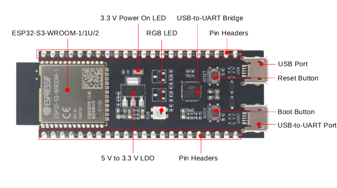
The DevKitC-1 has two micro-USB ports side by side, and they are not the same thing.
| Port | What it does |
|---|---|
| UART (left) | Goes through the on-board CP2102 bridge. The classic route, always works |
| USB (right) | Wired straight to the chip’s USB-OTG peripheral. Flashing, serial, and JTAG debugging |
The beginner story is always the same: plug into the right-hand port, write Serial.println(), see nothing in the serial monitor.
To get Serial.print output over the native USB port, you must set Tools → USB CDC On Boot → Enabled in the Arduino IDE. It is off by default.
Once enabled there is a second trap: every time the board resets, the USB connection drops and re-enumerates. The first lines in setup() never make it to the monitor. The fix:
void setup() {
  Serial.begin(115200);
  delay(2000);   // wait for USB to re-enumerate on the host
  Serial.println("Hello ESP32-S3");
}
Still nothing? Use the left-hand UART port. It doesn’t have this problem.
If the board doesn’t show up at all: hold BOOT, press and release RESET, then release BOOT. That forces download mode and the port appears.
Getting Started with the Arduino IDE
If you don’t have the Arduino IDE yet, start with our Arduino IDE download guide.
1. Add board support. File → Preferences → Additional Board Manager URLs:
https://espressif.github.io/arduino-esp32/package_esp32_index.json
2. Install the core. Tools → Board → Boards Manager → search “esp32”, install the Espressif Systems package.
3. Pick the right board. Tools → Board → ESP32 Arduino → ESP32S3 Dev Module. If your board has its own entry (XIAO, LilyGO), choose that instead.
4. Set the options. The ones that matter:
| Setting | Value |
|---|---|
| USB CDC On Boot | Enabled (if using the native USB port) |
| Flash Size | Your board’s actual size (16MB for an N16) |
| PSRAM | OPI PSRAM (for R8/R16) or Disabled |
| Partition Scheme | Something that matches the flash size |
| Upload Mode | UART0 / Hardware CDC |
5. Flash your first sketch. A test that drives the on-board RGB LED:
// ESP32-S3-DevKitC-1 v1.1 -> RGB LED on GPIO38
// ESP32-S3-DevKitC-1 v1.0 -> RGB LED on GPIO48
#define RGB_PIN 38

void setup() {
  Serial.begin(115200);
  delay(2000);
  Serial.printf("Flash: %u MB\n", ESP.getFlashChipSize() / (1024 * 1024));
  Serial.printf("PSRAM: %u bytes\n", ESP.getPsramSize());
}

void loop() {
  neopixelWrite(RGB_PIN, 32, 0, 0);   // red
  delay(500);
  neopixelWrite(RGB_PIN, 0, 32, 0);   // green
  delay(500);
  neopixelWrite(RGB_PIN, 0, 0, 32);   // blue
  delay(500);
}
If the serial monitor prints your flash and PSRAM sizes, the board is configured correctly. PSRAM reporting 0 means you forgot to enable it in the Tools menu.
Two revisions of the DevKitC-1 are on the market. v1.0 wires the RGB LED to GPIO48, v1.1 to GPIO38. Espressif states this explicitly in the revision notes.
If your code is right but nothing lights up, try the other pin. On clone boards the number can be something else entirely, so check that board’s own schematic.
When Should You Pick the ESP32-S3?
Pick it when:
- You are driving a color TFT or a large OLED (the LCD interface and PSRAM exist for this)
- You need a camera (the DVP interface is built in)
- You are recording or playing audio over I2S
- You want native USB (HID keyboard, MIDI device, serial)
- You are running out of pins
- You are running a small neural network on the edge
Skip it when:
- You need Bluetooth Classic (not on the S3)
- You need a DAC for analog output (not on the S3)
- You need wired Ethernet (no MAC on the S3)
- Your project just reads a sensor and posts to the cloud. An ESP32-C3 is cheaper and draws less power for that.
If displays are your thing and you need custom glyphs, our LCD character generator and image-to-C-array converter will save you time.
The Bottom Line
The ESP32-S3’s learning curve is steeper than the classic ESP32’s, but the steepness comes from choice, not difficulty: two USB ports, five module variants, a PSRAM setting you have to remember, an LED pin that moves between revisions.
Know these four things and the rest follows:
- N and R are flash and PSRAM; don’t forget to enable PSRAM in the menu.
- The right-hand USB port needs
USB CDC On Bootenabled. - GPIO35-36-37 are dead on common variants, GPIO19-20 belong to USB.
- With Wi-Fi on, read analog from ADC1, meaning GPIO1 through GPIO10.
👉🏻 When you need to look up a pin, our ESP32 pinout tool shows five boards including the S3 side by side.