Getting Started
This is 1-2. The guide is the most up-to-date and is a huge guide prepared by collecting and researching almost all the sources, especially about the 16x2 LCD and the history of LCD. With the information you will learn, you will be able to understand how the LCD you will see in one place works, and you will be able to do it. Let’s get started right away. 🙂
What is LCD?
LCD, Liquid Crystal Display, is an imaging technology based on the principle that the electrically polarized liquid passes the light in a single phase and can be seen with a polarization filter added to the front.
The liquid crystals found in LCDs can be found in thermographic and lyotropic phases according to temperature and substance structure. Nematic liquid crystals, a subgroup of thermographic phase liquid crystals, called twisted nematic (TN), become nematic that are not curved to a flat position depending on the voltage of the applied current. Nematic liquid crystals are the liquid crystal phase that makes it possible to make LCDs. In order for LCDs to be made, light must be polarized, liquid crystals must be able to pass polarized light, the molecular arrangement of liquid crystals must be replaced by electric current, and a structure that conducts electricity must be obtained.
LCD Structure and Working Principle
Yes, let’s start by giving you some information about the structure and working principle of LCD.
LCD stands for Liquid Crystal Display. It is a type of display unit that uses liquid crystals to create images.
When an electric current is applied to these special crystals, they become opaque by blocking the backlight behind the screen. As a result, pixel areas can appear darker compared to others. You can understand this better by examining the photo below.
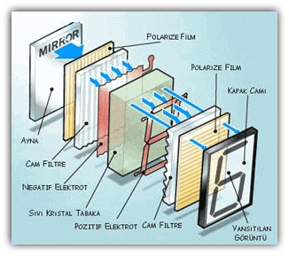
The display has an LED backlight and can display 32 ASCII characters on two lines, 16 characters per line. The structure of LCDs consists of different layers, as seen in the picture above.
When the LCD layers come together, the panels are formed. The working logic of the panels in their simplest form is that the specialized cells on the ion layer shape them and the image is created with electric current.
Before any electric field is applied, the liquid crystals are arranged in so-called curved nematics (TN), which are curved 90 degrees. This causes the polarization of light passing through the crystals to change direction and the screen appears gray. When a sufficiently high voltage is applied, the liquid crystals are arranged untwisted and the polarization direction of the light does not change as it passes through the liquid crystal layer. In this case, the light is polarized perpendicular to the second filter and the pixel appears black because it cannot pass through the layer.
The 16x2 LCD Screen: A Quick Overview
The screen we are going to use is a 16×2 LCD screen, which you can get at an affordable price. The fact that the screen is called 16×2 means that the LCD has 2 lines and can display 16 characters per line. So the screen can display 32 characters at the same time. You can also scroll to view more than 32 characters.
How does 16x2 LCD Screen Work?
- It works with +5V.
- It has a Back Lighting feature.
- It draws a 4mA current without LCD backlight.
- Its dimensions are 80x36x9.4mm.
- The operating temperature is from -20 to +70 degrees.
LCD Pins
Presently LCD panels produced today have 16 pins in a single row. The first 14 of these pins are used for control and it used the last two for the backlight, if any. The 14 pins used for control on some LCDs can also be found in 2 rows of 7.
Most LCDs come with a built-in series resistor for the LED backlight. If your LCD doesn’t have one, you need to add a resistor between pin 15 and 5V.
To calculate the value of the series resistor, you can refer to the datasheet for the maximum backlight current and typical backlight voltage drop, and use Ohm’s Law to determine the resistor value.
If you can’t find the datasheet, using a 220-ohm resistor is generally safe, but be aware that this higher value might slightly dim the backlight.
| PIN NO | FUNCTION | NAME |
|---|---|---|
| 1 | Grounding (0v) | Ground |
| 2 | Supply voltage(+5v) | VCC |
| 3 | Potentiometer Introduction (To Adjust the LCD Configuration) | VO |
| 4 | Command Register Data Register to switch between ⭐ | RRegister Select |
| 5 | Read/Write to LCD operations used for ⭐⭐ | Read/Write |
| 6 | The process of writing to the Register enabling pin | Enable |
| 7 | 8 Bit Data Pins ⭐⭐⭐ | DB0 |
| 8 | 8 Bit Data Pins ⭐⭐⭐ | DB1 |
| 9 | 8 Bit Data Pins ⭐⭐⭐ | DB2 |
| 10 | 8 Bit Data Pins ⭐⭐⭐ | DB3 |
| 11 | 8 Bit Data Pins ⭐⭐⭐ | DB4 |
| 12 | 8 Bit Data Pins ⭐⭐⭐ | DB5 |
| 13 | 8 Bit Data Pins ⭐⭐⭐ | DB6 |
| 14 | 8 Bit Data Pins ⭐⭐⭐ | DB7 |
| 15 | Voltage Adjustment of Backlight | Led + |
| 16 | Voltage Adjustment of Backlight | Led - |

LCD Pin Descriptions:
⭐ RS Pin is LOW (0), it selects Command Register, and when RS Pin is HIGH (1), it selects Data Register.
Command Recording: Command recording records the command instructions given to the LCD. A command is an instruction to the LCD to perform a predefined task.
For example:
- Starting the screen,
- Cleaning the screen,
- Setting the cursor position, etc.
Processing of commands occurs in the command recording.
When we return LOW (0) to the ⭐⭐ R/W Pin, the write operation performs a read operation when we send a HIGH (1).
⭐⭐⭐ These Pins send data or commands to the LCD.
Data Record: A data record stores the data to be displayed on the LCD. The data is the ASCII value of the character to be displayed on the LCD. When we send data to the LCD, the data goes to the record and is processed there. When RS = 1, data logging is selected.
Let’s take look at what all the pins do, so we can understand better.
GND: It must be connected to any GND pins of the Arduino. This pin (minus) is the pin where the grounding connection will be made.
VCC: We must connect it to a 5 volt pin on the Arduino. The LCD will get its electricity from here.
VO (LCD Contrast): We must connect it to any GND pins in the Arduino. This pin (minus) is the pin where the grounding connection will be made.
Pin RS (Register Select): allows the Arduino to tell the LCD whether it is sending commands or data. Basically, this pin is used to separate commands from data. R/W (Read/Write): To check if you can read data from the LCD or write data to the LCD.
E (Enable): Used to activate the screen. That is, when this pin is set to LOW, the LCD cares about what happens on the R/W, RS, and bus lines; when this pin is set to HIGH, the LCD processes incoming data.
D0-D7 (Data Bus): are the pins that carry the 8-bit data we send to the screen. For example, if we want to see the character ‘A’ on the screen, we can display these pins by typing 0100 0001 (according to the ASCII table) on the LCD, but let’s continue with this topic yet. 😄
A-K (Anode & Cathode): are used to control the LCD’s backlight.
LCD Commands:
| Serial No. | Hex Code | LCD Screen Equivalent |
|---|---|---|
| 1 | 01 | Clear Screen |
| 2 | 02 | Back to Top of Line |
| 3 | 04 | Move Cursor to Left |
| 4 | 06 | Move Cursor to Right |
| 5 | 05 | Screen Scroll Right |
| 6 | 07 | Screen Scroll Left |
| 7 | 08 | Screen off, cursor off |
| 8 | 0A | Screen on, cursor on |
| 9 | 0C | Display on, cursor off |
| 10 | 0E | The screen is on, the cursor is flashing |
| 11 | 0F | The screen is on, the cursor is flashing |
| 12 | 10 | Move cursor position left |
| 13 | 14 | Move cursor position right |
| 14 | 18 | Swipe all screen left |
| 15 | 1C | Scroll all screen to the right |
| 16 | 80 | Force cursor to head (line 1) |
| 17 | C0 | Force cursor to head (2nd row) |
| 18 | 38 | 2 rows and 5×7 matrices |
Pixels:
If you look closely at the photo below, you can see a pixel on the screen, namely its small rectangles and the pixel that makes up a character.
Each of these rectangles is a grid of 5×8 pixels, in which we see a pixel in the photo. Although they only display text, they come in a number of sizes and colors: for example, 16x1, 16x4, 20x4 white text appears on a blue background, and black text appears on a green screen. The LCD screen is 16x2 in size and can show 16x2=32 characters.
It expressed each character in 8x5=40 pixels, consisting of 5 columns and 8 lines.

Now we know that each character (5x8 = 40) has 40 pixels, and for 32 characters (32x40) we will have 1280 pixels.
In addition, it is necessary to inform the LCD about the location of the pixels. If we try to do it through the microcontroller we use in such works, we will tire the microcontroller we have. We perform such tasks with the LCD’s HD44780 interface to perform the task of receiving commands and data from the microcontroller and displaying it on the LCD screen.
The function of this IC (i.e. integrated circuit) is to receive commands and data from the MCU (i.e. the microcontroller unit) and process them in such a way as to display meaningful information on our LCD screen.
Many LCDs use the HD44780 interface. You can learn all the information about the Hitachi HD44780 to program the LCD screens. Click here to find this information.
Now let’s turn the back of our 16×2 LCD screen and see what’s going on here.
What Is the Task of Black Circles Behind the LCD Screen?
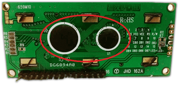
These black circles behind our LCD screen act as a bridge between our microcontroller and the LCD. It consists of an interface IC and its related components to help us use the LCD with the MCU.
Displaying Special Characters on a 16x2 LCD
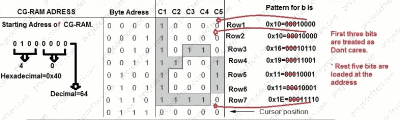
Creating special characters on an LCD is not so difficult. It requires knowledge of the LCD’s specially created random access memory (CG-RAM) and the LCD chip controller. Most LCDs have a Hitachi HD4478 controller.
The CG-RAM address starts at 0x40 (hexadecimal) or 64 in decimal. We can generate special characters in these addresses. Once we have created our characters at these addresses, we can simply print them by sending commands to the LCD. The following are the character addresses and printing commands.
| CG-RAM Characters | CG-RAM Address (Hexadecimal) | Generated Characters Display Commands |
|---|---|---|
| 1ˢᵗ | 0x40 | 0 |
| 1ˢᵗ | 0x48 | 1 |
| 1ˢᵗ | 0x56 | 2 |
| 1ˢᵗ | 0x64 | 3 |
| 1ˢᵗ | 0x72 | 4 |
| 1ˢᵗ | 0x80 | 5 |
| 1ˢᵗ | 0x88 | 6 |
| 1ˢᵗ | 0x96 | 7 |
In the table above, you can see the starting addresses for each character, along with the print commands.
The first character is created at addresses 0x40 to 0x47 and printed on the LCD by sending only the 0 command.
The second character is created in addresses 0x48 to 0x55 and is printed by sending a command 1.
How to Create Special Characters in CG-RAM?
Can create your own special characters (glyphs) and symbols for your LCD. They are extremely useful when you want to display a character that is not part of the standard ASCII character set.
LCD screens based on the Hitachi HD44780 controller have two types of memory known as CGROM and CGRAM (Character Generator ROM and RAM). CGROM is non-volatile and fixed, while CGRAM is volatile and can be changed at any time.
CGROM is used to store all the permanent fonts that can be displayed using ASCII codes. For instance, writing 0x41 will display the character ‘A’ on the screen.
CGRAM is essential for creating custom characters. It stores the special characters defined in the code. CGRAM has a size of 64 bytes, allowing for the creation of eight characters at a time, with each character being eight bytes in size.
CGRAM addresses start at 0x40 (64 in decimal). You can create special characters at these addresses, and then simply send commands to the LCD to display them. Character addresses and printing commands follow the format shown in the table above.
On LCD screens, each character is a 5×8 matrix. Where 5 is the number of columns and 8 is the number of rows.
Let’s make a simple example of how to create the letter ‘B’.
To form the letter ‘B’: char b [7] = {0x10, 0x10, 0x16, 0x19, 0x11, 0x11, 0x1E}; That is
We send the address where you want to create a character. So how can we make a special character for ourselves? By clicking on this link, you can make your own special characters, symbols, etc. Your imagination is limitless. Can also make any language characters you want in symbols or letters that we can do.
The LCD screen standard character list does not contain specific letters (ğ, İ, ö, ü, ç, ş).
Of course, we will not write using hex codes, it will be easier for us to use it with microcontrollers such as Arduino, etc. using binary codes.
International characters have specific ASCII codes. For example, we use the character ‘A’, but the microcontroller takes the character data ‘A’ and converts it to the number 61 and compares it by looking at the character set, then we see the letter ‘A’ on our screen.
Since ASCII characters are standard, they work in the following order: When we type the character ‘A’, the microcontroller converts the character ‘A’ to the number 61 consisting of 1 and 0’s, that is, it sends these ‘01100001’ bits to the LCD. Now I hope you understand why we shouldn’t write using bits… 😄 The LCD takes this binary code and converts it into data 61, then looks at the LCD character set, which is the equivalent of 61. This is the ‘A’ character. This is how events proceed in the ASCII standard, you can see the LCD’s character set below.
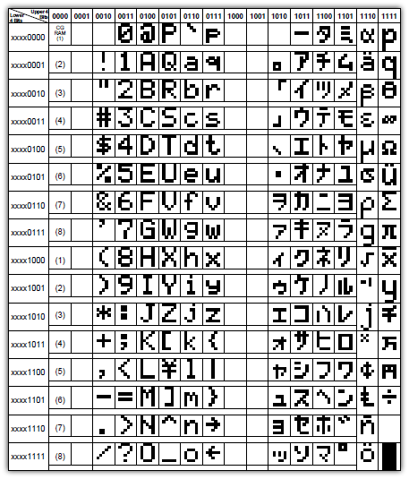
The characters we create start from the top left (where it says CGRAM(1)) and settle down to 8 lines. If you look at the character ‘A’ in the table, we see that it has an address of “01100001”, that is, 61. Now that we know the 16x2 LCD and understand how it works, in the second post we will try to understand coding and how it works virtually. Stay safe… 🤗