Hello everyone! In this article, we will connect a 16x2 LCD to Arduino over I2C. Using an I2C LCD with Arduino cuts the wiring from 12+ pins down to just 4 (VCC, GND, SDA, SCL), which keeps your projects much cleaner. Let’s get started!
Read This!
If you want to learn more about the 16x2 LCD Screen in more detail and how to use it without I2C, you can find out by clicking here. This blog will also be supported with guide blogs. ✨
What is an I2C Adapter?
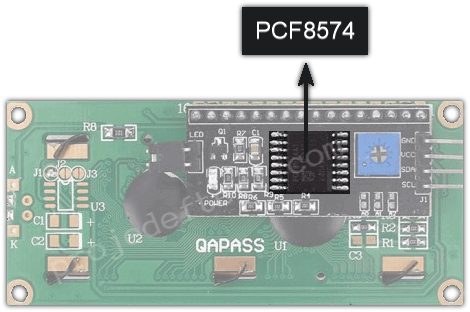
The I2C chip has an 8-Bit I/O Extender chip-PCF8574. This chip converts the I2C data from an Arduino into parallel data required by the LCD screen.
The I2C also has a small trim pot to fine-tune the display’s contrast. You can adjust its brightness by turning it with a screwdriver.
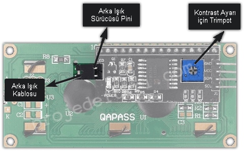
In addition, the I2C has a pin cable that supplies power to the backlight. To control the intensity of the backlight, you can remove the cable and apply an external voltage to the head pin marked “LED”.
Without going into more detail, let’s move on to the way it is linked.
Arduino I2C LCD Connection
The I2C LCD module connects to Arduino with only four wires: VCC to 5V, GND to GND, SDA to A4 and SCL to A5 (on an Arduino Uno).
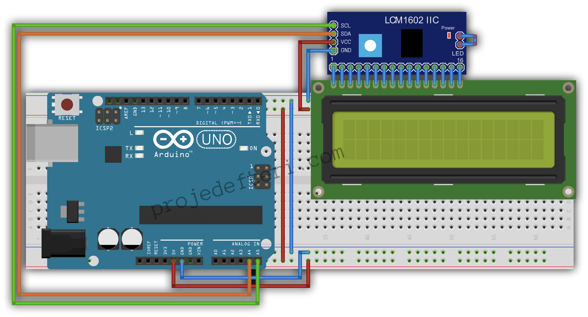
The SDA and SCL pins sit somewhere different on every board. Find yours:
| Board | SDA | SCL | VCC |
|---|---|---|---|
| Arduino Uno / Nano | A4 | A5 | 5V |
| Arduino Mega 2560 | 20 | 21 | 5V |
| Arduino Leonardo / Micro | 2 | 3 | 5V |
| ESP32 (default) | GPIO21 | GPIO22 | 5V (VIN) |
| ESP8266 / NodeMCU | D2 (GPIO4) | D1 (GPIO5) | 5V (VIN) |
| Raspberry Pi Pico | GP4 | GP5 | VBUS (5V) |
If you are not sure which pins are I2C on your board, check the Arduino Pinout and ESP32 Pinout references.
Find the Right I2C Address
This is the step people get stuck on. Modules answer at either 0x27 or 0x3F, with exceptions. The wrong address raises no error at all, the screen simply stays blank. Scan instead of guessing:
#include <Wire.h>

void setup() {
  Wire.begin();
  Serial.begin(9600);
  while (!Serial);
  Serial.println("Scanning I2C...");

  byte found = 0;
  for (byte address = 1; address < 127; address++) {
    Wire.beginTransmission(address);
    if (Wire.endTransmission() == 0) {
      Serial.print("Device found at 0x");
      if (address < 16) Serial.print("0");
      Serial.println(address, HEX);
      found++;
    }
  }
  if (found == 0) Serial.println("Nothing found. Check the wiring.");
}

void loop() {}
Open the serial monitor at 9600 baud and put whatever address it prints into the LiquidCrystal_I2C lcd(...) line. If no device shows up at all, the problem is the wiring or the supply, not the code.
Arduino IDE Library Setup
If you don’t know how to set up a library, you can check out this page.
Download the LiquidCrystal I2C library by Frank de Brabander by typing liquidcrystal instead of searching for a library. If you can’t find it, quickly download it from this link (it downloads as soon as you click it) and add it as a ZIP. (Downloading from Arduino site.) Here’s a quick rundown on how to add it as a ZIP.
Arduino I2C LCD Code Example
#include <LiquidCrystal_I2C.h> // added the library

LiquidCrystal_I2C lcd(0x3F,16,2);  // for a screen of 16 characters and 2 lines, the LCD address is set to 0x3F.

void setup() {
  lcd.init();
  lcd.clear();
  lcd.backlight();      // backlight on
  lcd.setCursor(2,0);   // 3 rows to the right, 1 column down
  lcd.print("projedefteri.com");
}

void loop() {
}
Library Functions
Everything LiquidCrystal_I2C can do is in the list below. For a 20x4 display just change the constructor to lcd(0x27, 20, 4); nothing else differs.
| Function | What it does |
|---|---|
lcd.init() | Initialises the display. Must be the first call in setup(). |
lcd.backlight() / lcd.noBacklight() | Turns the backlight on / off. |
lcd.clear() | Wipes the screen and returns the cursor home. |
lcd.home() | Moves the cursor to the top left without clearing. |
lcd.setCursor(column, row) | Positions the cursor. Zero based: top left is (0, 0). |
lcd.print(...) | Prints text, numbers or variables. |
lcd.cursor() / lcd.noCursor() | Shows / hides the underline cursor. |
lcd.blink() / lcd.noBlink() | Blinking block cursor. |
lcd.display() / lcd.noDisplay() | Turns the image off without losing the content. |
lcd.scrollDisplayLeft() / Right() | Shifts the whole content one character. |
lcd.createChar(index, bytes[]) | Loads a custom glyph into slot 0-7. |
lcd.write(index) | Prints a custom glyph. |
lcd.setCursor(2, 1) means the third column of the second row, not the second column of the third row. Getting this backwards is why text seems to vanish. On a 16x2 the valid range is 0-15 for the column and 0-1 for the row.Scrolling Text
Sixteen characters is not much. There are two approaches.
1. The library’s own scroll. It shifts the entire display, which is fine for short messages:
void setup() {
  lcd.init();
  lcd.backlight();
  lcd.setCursor(0, 0);
  lcd.print("Proje Defteri - Arduino guides");
}

void loop() {
  lcd.scrollDisplayLeft();
  delay(300);
}
2. Scrolling your own window. More control, and it works per row:
String message = "Temp 23.4 C, Humidity 48%, Pressure 1013 hPa   ";
int pos = 0;

void loop() {
  lcd.setCursor(0, 0);
  lcd.print(message.substring(pos, pos + 16));

  pos++;
  if (pos > message.length() - 16) pos = 0;

  delay(300);
}
Note there is no lcd.clear() here. Because we print exactly 16 characters every time, the old content is already overwritten; adding clear() produces visible flicker.
Custom Characters
The HD44780 controller reserves eight custom character slots, 0 to 7. Each one is a 5x8 pixel glyph described by eight bytes.
byte degree[8] = {
  0b00110,
  0b01001,
  0b01001,
  0b00110,
  0b00000,
  0b00000,
  0b00000,
  0b00000
};

void setup() {
  lcd.init();
  lcd.backlight();
  lcd.createChar(0, degree);      // load into slot 0

  lcd.setCursor(0, 0);
  lcd.print("Temp: 23.4");
  lcd.write(byte(0));             // the degree sign
  lcd.print("C");
}
The eight slot limit is real. If you need more, you can reload slots at runtime with createChar(), but that changes any glyph currently on screen too.
Troubleshooting
Blank screen but the backlight is on
Contrast. Turn the blue trim pot on the back of the module slowly with a screwdriver. It often ships near zero, which shows nothing at all.
Only a row of solid white blocks
The classic symptom: the panel works but the Arduino is not talking to it. Usually the wrong I2C address, or lcd.init() was never called. Run the scanner sketch.
Not even the backlight comes on
A supply problem. Check VCC and GND, and on ESP boards make sure you are using 5V rather than 3.3V. If the module has a backlight jumper, confirm it is fitted.
Text appears but the characters are garbled
Usually an inadequate supply or overly long wires. The I2C bus degrades past roughly 20 to 30 cm. If you have hung many sensors off the same bus, the pull-up resistors may also be insufficient.
If you want to show your own custom characters (special symbols, accented letters, etc.) on the screen you wired up over I2C, our LCD Custom Character Generator builds the byte array you need in seconds.
Frequently Asked Questions
Which pins does an I2C LCD use on Arduino? On an Arduino Uno the I2C LCD uses A4 (SDA) and A5 (SCL), plus 5V and GND. On an Arduino Mega, SDA is pin 20 and SCL is pin 21.
My Arduino I2C LCD shows nothing. What should I check? First adjust the contrast trim pot on the back of the I2C module. Then verify the I2C address: most modules use 0x27 or 0x3F. If neither works, run an I2C scanner sketch to find the correct address.
What is the I2C address of a 16x2 LCD? It depends on the chip on the adapter: PCF8574 modules usually respond at 0x27, PCF8574A modules at 0x3F. The address goes into the constructor, for example LiquidCrystal_I2C lcd(0x27,16,2);.
Which library do I need for an Arduino I2C LCD? The LiquidCrystal_I2C library. Install it from the Arduino IDE Library Manager or add it as a ZIP as shown above.
Does the same code work with a 20x4 LCD? Yes. The only change is the constructor: LiquidCrystal_I2C lcd(0x27, 20, 4);. Every function stays the same, only the setCursor range grows to 0-19 for the column and 0-3 for the row.
Can I put other sensors on the same I2C bus? Yes, that is the whole point of I2C. Wire them in parallel on SDA and SCL, as long as their addresses differ. An LCD uses 0x27, a BME280 uses 0x76, a DS3231 uses 0x68, so they coexist happily. Two devices with the same address need a multiplexer such as the TCA9548A.
How do I scroll text on an I2C LCD? Two ways: lcd.scrollDisplayLeft() shifts the whole display, or you can slide a 16 character window over a longer string yourself with substring(). The second is more useful because it works per row; there is example code in the scrolling section above.
Should I use an I2C LCD or an OLED? If you are only showing text, an I2C LCD is cheaper, more readable and uses almost no RAM. If you want graphics, icons or animation you need an SSD1306 OLED, at the cost of 1 KB of RAM on an Arduino Uno. See the Arduino OLED SSD1306 tutorial for that side.
If you have had any problems, do not forget to check your links, or you can send your questions, comments, and suggestions from the comments! Happy coding! 😁
Related Tools and Reading
- LCD Custom Character Generator - design 5x8 glyphs and get the
createChar()code - I2C LCD Code Generator - produce ready LiquidCrystal_I2C sketches
- Arduino Pinout - find the I2C pins on your board
- The 16x2 LCD big guide - the parallel wiring route, without I2C
- Arduino OLED SSD1306 Tutorial - the graphic display side